
Section 4: Control Page/Control Scenarios
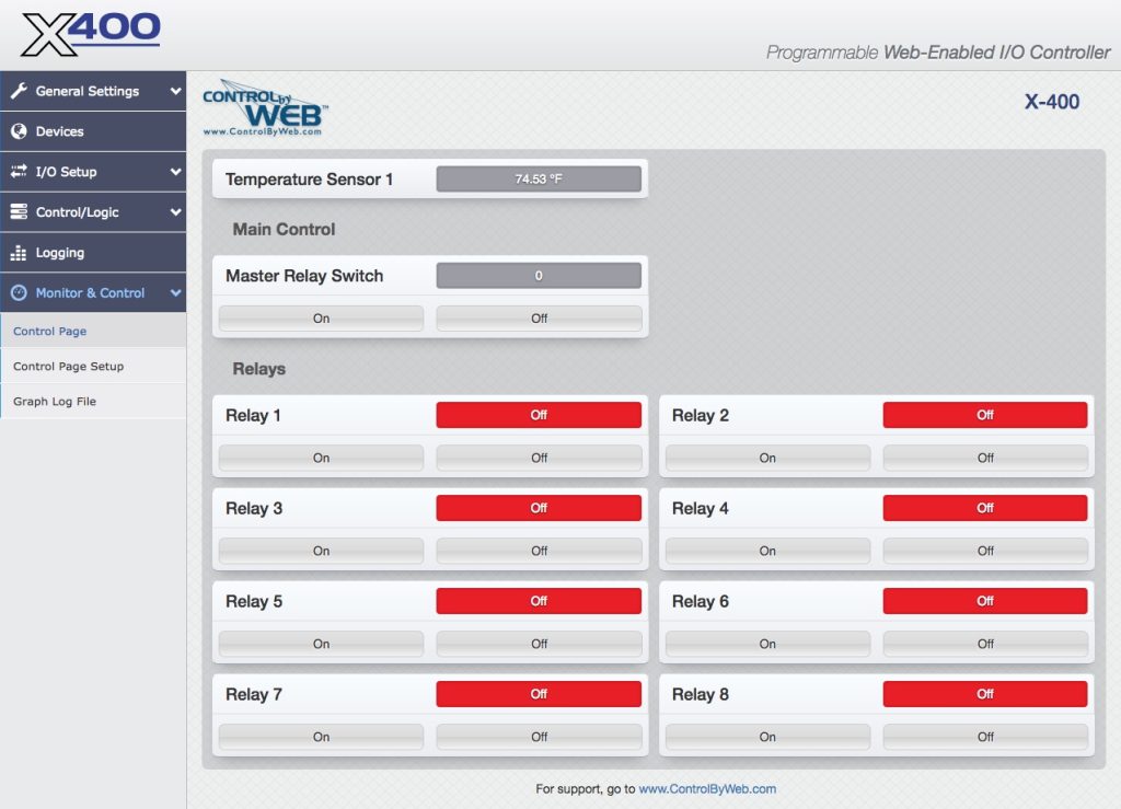
The Control Page is normally what users see and use, and it can be highly configured to fit your needs. The Monitor & Control Tab > CONTROL PAGE SETUP tab has settings that determine what resources are displayed and how they are formatted.
Administrators, Managers, and Users have separate access privileges to the Control Page. See Error: Reference source not found for a description of each access privilege.
4.1 Browser Operation
There are two ways users can access the Control Page by using a web browser:
1. Control Page
The first is by typing the IP address of the module directly into the web browser address bar. For example, using the default IP address, the user would enter http://192.168.1.2 (If the IP address was changed from the default, the user must use the new IP address.)
Note that if any port is used other than the default port 80, the port must also be included in the request.
For example, accessing the unit at port 8000 would be as follows: http://192.168.1.2:8000
To access the module using HTTPS, the user would enter: https://192.168.1.2
If any port is used other than the default HTTPS port 443, the port must also be included in the request. You will usually get a warning when accessing the module over HTTPS, this is because the module is using a default, self-signed SSL certificate.
The I/O on the Control Page updates every three seconds unless the update interval has been changed in the Control Page Setup.
2. Control Page via Setup Page Tabs
The second method of accessing the Control Page is through the Setup Page tabs (http://192.168.1.2/setup.html).
Choose Monitor & Control Tab > CONTROL PAGE.
This section presents various control examples using Scheduled Tasks, Conditional Tasks, and BASIC scripts to solve example applications.
4.2 Control Logic Examples Using Tasks/Functions
The following examples illustrate tasks or functions that can be performed by the module. These examples may be used as a tutorial to illustrate how to perform certain functions and can be a good starting point for more advanced logic.
Important: When creating tasks that perform actions when something is triggered, the action will not automatically reverse when the trigger goes away. For example, if a trigger turns a remote digital output on when temperature rises above 50 degrees, you must create a second task to turn the digital output off when the temperature falls below 50 degrees.
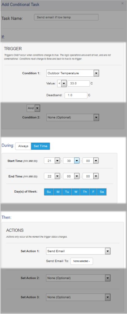
4.2.1 Send an email if the temperature is less than 33 °C between 9:30 PM and 10 PM each day
In this example, the Dead-band of 1 degree was used to prevent multiple email messages being sent due to “chatter”.
Another email message won’t be sent until the temperature rises above 34 degrees (33 plus 1 degree deadband) and then back below 33 degrees.
The “During” section of the task limits the time when the triggers are effective to 9:30 P.M. and 10:00 P.M. every day of the week. Outside this window, email messages will not be sent even if the temperature drops below 33 degrees.
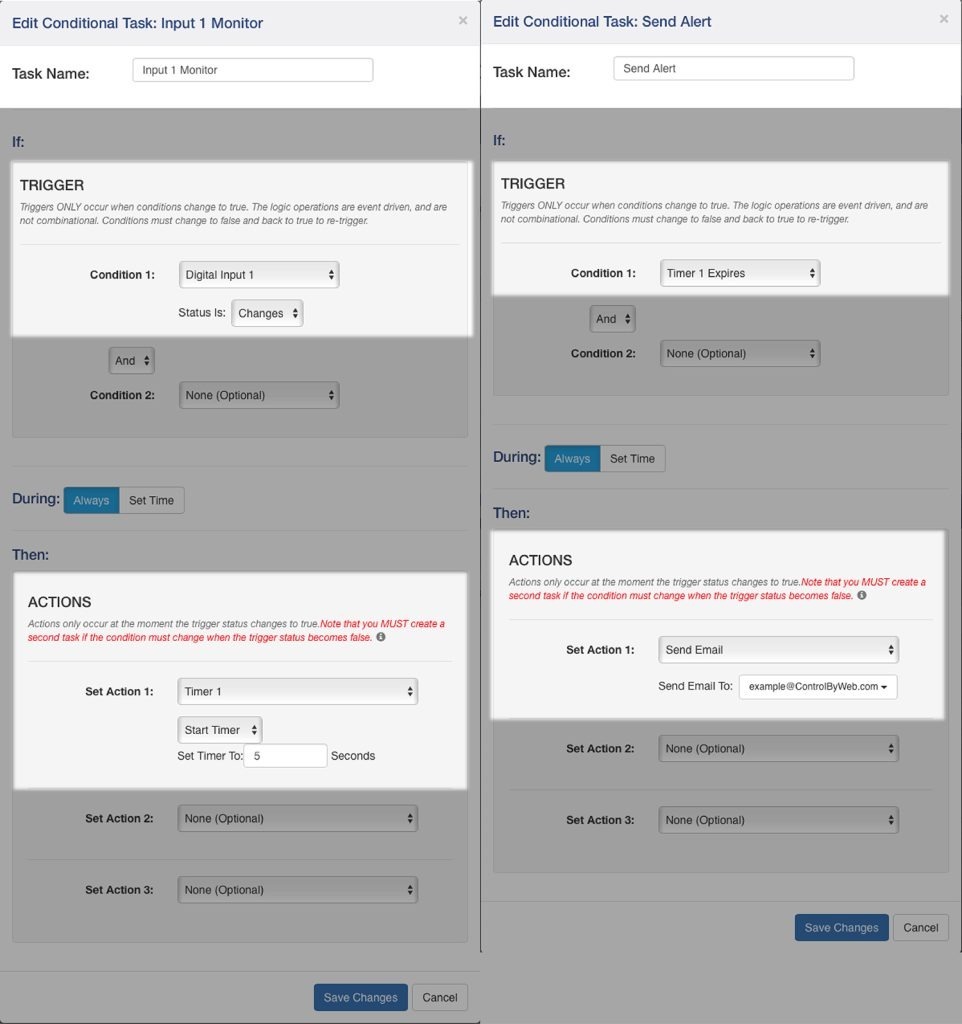
4.2.2 Send Email if Input 1 stops toggling
Monitor Pseudo Digital Input 1 for state changes. If Input 1 doesn’t change state every 5 seconds or faster, an email message will be sent.
This is using two tasks. Task 1 starts (or re-starts) a timer each time the pseudo input changes. Task 2 sends the alert if the timer ever expires.
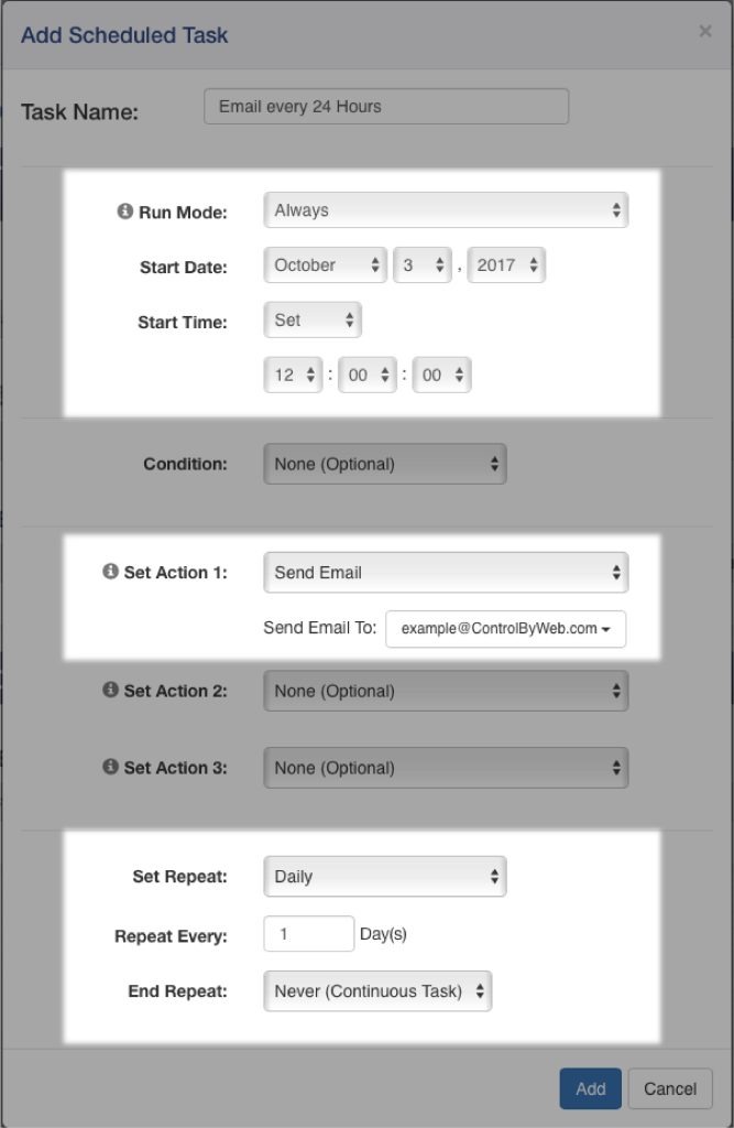
4.2.3 Send an email message every 24 hours
4.2.4 Network monitor between two X-400 modules (advanced)
In this example, we will configure two X-400 devices to share a register. In the example we are using this as a network monitor, but this example illustrates how to share register or I/O states between modules.
One X-400 (we will call X-400_ONE) will be configured to share a register with a second X-400 (we will call X-400_TWO). X-400_ONE will change that register value once every 10 seconds. X-400_TWO will monitor that register value. If X-400_TWO detects no changes to the register for more than 12 seconds, it will send an email alert.
Setup X-400_ONE communications with X-400_TWO:
- Connect both devices to the network and assign an IP address to each of them.
- Open the setup page for X-400_ONE and select the “Remote Devices” tab. Click the “Find Devices” button. The other X-400 (X-400_TWO) should appear in the list. If multiple X-400 units are installed on the network, you may need to identify it by serial number. Select that X-400 device so the “Add Remote Device” window appears. Within that window…
- Name the device “X-400_TWO”
- Select Model X-400 (should already be selected)
- Serial number should be filled in with the correct serial number.
- IP address should have a correct IP address for X-400_TWO and the port should be correct.
- Set up the security options and enter passwords for X-400_TWO
- In the bottom portion of the window, select “Instant Send”
- Click “Add Device”
Wait a minute and then you should see X-400_TWO in the Remote Device List and the status should indicate a response time (in milliseconds) from the remote unit (the smaller the response time the better).
Now X-400_ONE is set up to push its I/O state to the remote device. By default, it will push the state every 3 seconds (PUSH interval) but we want it to push its state instantly when the register changes so we will set that up in Conditional Tasks.
Setup of X-400_ONE to toggle register and share it with X-400_TWO (add two Conditional Tasks):
- Open setup page for X-400_ONE (should already be there from above setup)
- Set up a timer (called Timer 1) with a Power Up value of 8 seconds. This timer will be used to change the register and the Power Up value will cause it to start automatically.
- Set up a task and call it “Toggle Register to 1”. Set the trigger to “Timer 1 Expires AND Register 1 = 0”. Set the Actions to “Set Register 1 to 1” and “Start Timer 1 for 10 Seconds” and “Push I/O State To Remote Receiver Device”
- Set up a task and call it “Toggle Register to 0”. Set the trigger to “Timer 1 Expires AND Register 1 = 1”. Set the Actions to “Set Register 1 to 0” and “Start Timer 1 for 10 Seconds” and “Push I/O State To Remote Receiver Device”
Setup of X-400_TWO to monitor the register from X-400_ONE and sent alert if the register doesn’t change within 12 seconds:
- Open setup page for X-400_TWO and select Remote Devices tab. You should see X-400_ONE in the list of devices but the name will show as the serial number rather than the name X-400_ONE. You can click edit and change the name to X-400_ONE. If the X-400_ONE device doesn’t appear in the list, you will need to add it to the list manually.
- Once the X-400_ONE device appears as one of the Remote Devices you will need to add its register to the local I/O. Click on I/O Setup, then Registers. At the bottom of the table, click on the button called “Add Remote Register”. Add the register “X-400_ONE Register 1” to the list. You should now see this new register listed under “Remote Register”.
- We need a timer to go to I/O Setup and create a timer called “Timer 1”. Give it a power up value of 30 seconds to make sure both X-400 units have plenty of time to boot before sending error messages.
- Now add the logic. Click on “Control/Logic” and create a new Conditional Task. Call this task “Set Timer When 1”. Set trigger Condition 1 to “X-400_ONE Register 1 = 1”. Set Action 1 to “Start Timer” with a time of 12 Seconds.
- Add a second Conditional Task. Call this task “Set Timer When 0”. Set trigger Condition 1 to “X- 400_ONE Register 1 = 0”. Set Action 1 to “Start Timer” with a timer of 12 Seconds.
- Add a third Conditional Task. Call this task “Send Alarm”. Set trigger Condition 1 to “Timer 1 Expires”. Set Action 1 to “Send Email” and specify the email address where the message should go (if no email addresses appear you will need to set them up first).
4.3 Control Logic Examples Using BASIC Scripts
Most advanced logic tasks can be accomplished using the module’s Task Builder; however, the module has a BASIC interpreter that can be used for more advanced tasks.
I/O resources are not fixed on the module. After registers and other I/O are added, they can be used within BASIC scripts. BASIC scripts must reference I/O resources such as digital I/O in the form of io.name where “name” is the resource name defined for each I/O under the I/O Setup Tab.
If the resource name has embedded spaces, they must be removed in the io.name statement. The first character must be lower case. For example, if a digital I/O is named “Warehouse Fan”, the fan can be turned on with the BASIC statement “LET io.warehouseFan = 1”. If a resource name is changed during development and testing, the resource name in the BASIC script must be renamed to match.
4.3.1 If an analog input is in the alarm state, send an email every hour
DO
‘If 2.5 < sensor1 < 4.5 then send an email every 1 hour
IF io.temp1 < 4.5 THEN
IF io.temp1 > 2.5 THEN
IF t0 = 0 THEN
LET t0 = 36000 ‘3600 seconds
END IF
END IF
END IF
LOOP
END
4.3.2 Monitor 4 doors, send an email if a door is open more than 5-minutes
Send an email if a door has been open for more than 5 minutes, repeat the email every 5 minutes thereafter while the door is open. Note, we use the digital input mode of the analog inputs for this scenario.
‘Send an email alert after a door has been open for more than 5 minutes.
‘Continuously set a timer for 5 minutes if the door is closed
‘Setting initial timer values
‘Using variables a-d allow simple changes to alarm times
LET a = 3000 ‘Input1 300.0 seconds
LET b = 3000 ‘Input2 300.0 seconds
LET c = 3000 ‘Input3 300.0 seconds
LET d = 3000 ‘Input4 300.0 seconds
LET t1 = a
LET t2 = b
LET t3 = c
LET t4 = d
‘Begin main program, sequentially service each door.
DO
‘If door1 is closed, then set timer for 5 minutes.
‘If door1 is open, then send an email and reset timer after timer expires
‘Door 1
IF io.analogInput1 = 1 THEN
LET t1 = a
ELSE ‘Else if door is open
IF t1 = 0 THEN
EMAIL io.analogInput1
LET t1 = a
END IF
END IF
‘Door2
IF io.analogInput2 = 1 THEN
LET t2 = b
ELSE ‘Else if door is open
IF t2 = 0 THEN
EMAIL io.analogInput2
LET b
END IF
END IF
‘Door3
IF io.analogInput3 = 1 THEN
LET t3 = c
ELSE ‘Else if door is open
IF t3 = 0 THEN
EMAIL io.analogInput3
LET t3 = c
END IF
END IF
‘Door4
IF io.analogInput4 = 1 THEN
LET t4 = d
ELSE ‘Else if door is open
IF t4 = 0 THEN
EMAIL io.analogInput4
LET t4 = d
END IF
END IF
LOOP
END
4.3.3 Send an email if the AC power fails
Send an email if the AC power (via input1) has been off for 60 seconds. Send a follow-up email when the power is restored. Send the power restored email only if a ‘power off’ email was previously sent.
Note: A simple AC to 12VDC wall transformer connected to the digital input can be used to detect the loss of AC power.
‘Script will send an email after power has been off for a specific amount of time.
‘Will also send an email when power is on only if a ‘power off’ email has been sent.
LET a = 0 ‘Power on email sent if true
LET b = 0 ‘Power off email sent if true
DO
IF io.input1 = 1 THEN ‘If power is on
LET t1 = 600
IF a = 0 THEN ‘If no ‘power on’ email has been sent
IF b = 1THEN ‘If ‘power off’ email has been sent
EMAIL io.input1
LET a = 1 ‘Set power on email sent flag
END IF
END IF
LET b = 0
END IF
‘Once power has been off a specific time
IF t1 = 0 THEN
IF b = 0 THEN
EMAIL io.input1
LET b = 1 ‘Set power off email sent flag
END IF
END IF
LOOP
END
4.3.4 Monitor a generator. Send an email if it runs for more than 10 seconds.
Send an email if a generator runs for more than 10 seconds, and every 30 minutes afterward. Send an email when the generator turns off if a ‘generator on’ email was sent.
‘Input1 is used as the source for the generator status
‘Input1 = 1 : Generator off
‘Input1 = 0 : Generator on
LET a = 0 ‘Generator on email sent flag
LET t1 = 100 ‘10.0 seconds
DO
‘Generator off
IF io.input1 = 1 THEN
LET t1 = 100 ‘10.0 seconds
IF a = 1 THEN ‘If generator on already email sent
EMAIL io.input1 ‘Email everything okay
LET a = 0 ‘Set generator on flag back to false
END IF
END IF
‘Generator on and timer expires
IF t1 = 0 THEN ‘If timer has expired
EMAIL io.input1 ‘Email generator on
LET t1 = 18000 ‘30 minutes until another email
LET a = 1 ‘generator on email flag
END IF
LOOP
END