
Integrating with ControlByWeb Devices
ControlByWeb devices easily integrate with other ControlByWeb and 3rd party devices. Multiple communication protocols can be used to integrate ControlByWeb devices with an existing system, including HTTP GET Requests (XML & JSON), Modbus and SNMP. External servers and the ControlByWeb Cloud allow for remote access and multi-device management. This manual will explain how to integrate ControlByWeb devices with 3rd party systems. Any additional information about each communication protocol will be found at a link provided at the beginning of their respective section.
For additional information related to the 400 series firmware, please refer to the 400 Series Users Manual or our support page (https://controlbyweb.com/support/) for additional help articles/support documents.
Section 1: HTTP GET Requests
1.1 HTTP GET Requests (for custom applications)
Each of the ControlByWeb modules has a built-in web server that responds to HTTP GET requests. The following section describes the HTTP protocol and how it can be used to control and monitor the module. All examples below show the state.xml, but will be the same for customState.xml and the JSON files. It is also assumed that a TCP/IP connection has already been established from the custom application to the device. The following are the messages that should be sent over the TCP/IP connection to control and monitor the device. The X-400 Series and X-600M can pull both XML and JSON files.
Additional information on HTTP Get Requests can be found at https://reqbin.com/Article/HttpGet
This section includes:
- HTTP Get Requests
- Using GET for Control and Monitoring
- Custom XML/JSON commands
- Understanding XML and JSON
- Log Files
1.1.1 Using GET for Control and Monitoring
There are 2 different options for using GET requests.
• Use a command line in the code
• Using the URL string
The primary method for using GET with ControlByWeb products adding a command line into the code. However, using the URL string can be can effective way of easily testing commands in a web browser.
No Password
GET requests to the device for XML files.
Example request state.xml:
GET /state.xml HTTP/1.1\r\n\r\n
Example set Register 1 to the value 25:
GET /state.xml?register1=25 HTTP/1.1 \r\n\r\n
Password Enabled
If the User account is enabled on the module, and the state.xml page is requested through a browser, the user will be prompted for a password. If the request is sent from custom application, the HTTP request will need to contain the password encoded as Base64.
The following is an HTML request header without the password:
GET /state.xml?register1=25 HTTP/1.1 (Terminated with two \r\n)
The following example adds the password:
GET /state.xml?register1=25 HTTP/1.1 (Terminated with one \r\n)
Authorization: Basic bm9uZTp3ZWJyZWxheQ== (Terminated with two \r\n)
bm9uZTp3ZWJyZWxheQ== is the Base64 encoded version of the user “name:password,” none:webrelay
1.1.2 Viewing/Controlling I/O with state.xml/json
The state.xml/json page served by an X-400 Series Device only shows the I/O that have been assigned a ‘Local I/O Number’. The XML/JSON tag names on this page represent the I/O type and Local I/O number on the X-400 Series device. For example, if two relays have the Local I/O Numbers 1 and 5 assigned and no other I/O on the X-400 Series device have a Local I/O Number assigned, then the state.xml/json page would appear as follows:
XML
<datavalues>
<relay1>0</relay1>
<relay5>0</relay5>
<vin>12.2</vin>
<utcTime>1262394580</utcTime>
<timezoneOffset>-25200</timezoneOffset>
<serialNumber>00:0C:C8:00:00:00</serialNumber>
</datavalues>
JSON
{
“relay1”:”0”,
“relay5”:”0”,
“vin”:”12.2”,
“utcTime”:”1262394580”,
“timezoneOffset”:”-25200”,
“serialNumber”:”00:0C:C8:00:00:00”
}
Notice that the power supply of the X-400 Series device ‘vin’ always appears in state.xml/json, as do the time, timezone, and serial of the X-400 Series device.
Reading state.xml/json
XML/JSON Monitor All Functions
The state of the I/O configured on the X-400 Series device can be read by requesting state.xml/json. This can be demonstrated by entering the following URL into the address bar of a web browser (substituting the IP address as necessary):
http://192.168.1.2/state.xml
http://192.168.1.2/state.json
Controlling with state.xml/json
Commands can be sent to the module to control the I/O. The parameters differ depending on whether state.xml/json is used or customState.xml/json is used. The state.xml/json command uses the I/O type names and local I/O numbers when controlling the I/O. The customState.xml/json command uses the Camel case version of the user configurable name when controlling the I/O.
XML/JSON Relay Control
Commands are sent using the parameter composed of the I/O type and relay number relay X (X is replaced by 1 for relay 1, or 2 for relay 2, etc). A few examples of using relay X are given below.
Note: The following examples showcase both XML and JSON examples. Replace XML with JSON or JSON with XML depending on the file type you’re looking for.
| Command | Description |
| state.xml?relay1=0 | Turn Relay 1 OFF |
| state.xml?relay1=1 | Turn Relay 1 ON |
| state.xml?relay1=2 | Relay 1 PULSE |
| state.xml?relay2=0 | Turn Relay 2 OFF |
| state.xml?relay2=1 | Turn Relay 2 ON |
| state.xml?relay2=2 | Relay 1 PULSE |
XML/JSON Pulse Relay
When the pulse command is sent, the output will turn ON for the Pulse Duration specified in the relay setup page. It is also possible to send a pulse time command that is different than the configured Pulse Duration. This is done by sending a pulseTime variable. The pulseTime variable does not change the Pulse Duration in the setup page and it is not stored or recorded. The pulseTime variable only changes the duration for the single pulse initiated by that command. In other words, you must issue the pulseTime command for each pulse command that differs from the preset value. For example, if the X-410 is configured for a pulse duration of 1.5 seconds. To issue one 1.5 second pulse, one 5 second pulse, and another 15 second pulse to relay 1, you would issue the following commands:
| Command | Description |
| state.json?relay1=2 | Pulse Relay 1 for the preset time (1.5 seconds). |
| state.json?pulseTime1=5&relay1=2 | Pulse Relay 1 for 5 seconds. |
| state.json?pulseTime1=15&relay1=2 | Pulse Relay 1 for 15 seconds. |
NOTE: The pulseTime argument MUST come before the relay1=2 command.
XML/JSON Set On Time
The on time and total on time values can be set using the onTimex and totalOnTimex commands respectively:
| Command | Description |
| state.xml?onTime1=0 | Reset the onTime1 to 0 |
| state.xml?onTime1=5 | Reset the onTime1 to 5 |
| state.xml?totalOnTime1=0 | Reset the totalOnTime1 to 0 |
| state.xml?totalOnTime1=5 | Reset the totalOnTime1 to 5 |
XML/JSON Set Counter
The counter values can be set using the countx command:
| Command | Description |
| state.json?count1=200 | Set counter1 to 200 |
XML/JSON Set Register Values
The register values can be set using the registerx command:
| Command | Description |
| state.xml?register1=10.5 | Set register1 to 10.5 |
1.1.3 Viewing/Controlling I/O with customState.xml/json
The customState.xml/json works very similarly to the state.xml/json page. The difference is in the customState.xml/json, the XML/JSON tag names are set to a name very similar to the name of the I/O it is associated with. For example, if you were to set the name of ‘Register 1’ to ‘My Register 1’ the register would show up in the customState.xml/json as ‘myRegister1’. Using these names allows applications interfacing with the module to use more appropriate names when reading and writing I/O values.
Controlling I/O with the customState.xml/json is the same as with the state.xml/json except you may now use the names shown in the XML/JSON tags. For example, if you wanted to set a register named ‘My Register 1’ to the value 10, you would use the following command:
http://192.168.1.2/customState.xml?myRegister1=10
http://192.168.1.2/customState.json?myRegister1=10
You will need to reference the customState.xml for the exact names to use for each of the configured I/O.
1.1.4 Sending multiple XML/JSON commands
Multiple XML/JSON arguments can be combined into a single command. This works with both customState.xml/json and state.xml/json commands. For example:
/customState.xml?relay1=1
/customState.xml?relay2=0
Can be combined into
/customState.xml?relay1=1&relay2=0
Or
/state.json?relay1=1
/state.json?relay2=0
Can be combined into
/state.json?relay1=1&relay2=0
1.2 XML
Custom computer applications may be created to monitor and control the module. This method does not use a web browser. Two XML pages, state.xml and customState.xml, can be used to monitor and control the module.
All requests to the XML files must be in the form of HTTP GET requests, see Section 1: HTTP GET Requests (for custom applications) for details.
Below is an example of an XML file that would be sent from your device:
<datavalues>
<digitalInput1>0</digitalInput1>
<onTime1>0.00</onTime1>
<totalOnTime1>0.00</totalOnTime1>
<count1>0.00</count1>
<frequency1>0.00</frequency1>
<relay1>1</relay1>
<relay2>0</relay2>
<relay3>0</relay3>
<relay4>0</relay4>
<analogInput1>4.96</analogInput1>
<analogInput2>4.96</analogInput2>
<analogInput3>4.97</analogInput3>
<analogInput4>4.97</analogInput4>
<oneWireSensor1>x.x</oneWireSensor1>
<vin>12.2</vin>
<register1>0</register1>
<utcTime>1262394580</utcTime>
<timezoneOffset>-25200</timezoneOffset>
<serialNumber>00:0C:C8:00:00:00</serialNumber>
</datavalues>
The numbers enclosed by the tags, <tag>, indicate the current state or value monitored by the module. Values for each tag are described in the table on the next page.
Custom computer applications can open a TCP/IP connection with the module and send a GET request for the state.xml file to obtain the module’s current state.
XML Tags and Monitor Values Table
| XML Tags | Monitor Values |
| <digitalInputX> | 0=off (voltage not applied to input X) 1=on (voltage applied to input X) |
| <onTimeX> | Time in seconds how long the input was on since last coming on |
| <totalOnTimeX> | Total time in seconds how long the input has been on |
| <countX> | The count value associated with input X |
| <frequencyX> | The frequency associated with input X |
| <relayX> | 0=off (coil off) 1=on (coil energized) |
| <digitalIOX> | 0=off (voltage not applied to input X) 1=on (voltage applied to input X) |
| <analogInputX> | Value of analog input X |
| <vin> | Scaled internal Vin measurement |
| <frequencyInput> | Value of the X-420 frequency input |
| <registerX> | Value of the register X |
| <utcTime> | Current UTC time expressed in seconds since January 1st, 1970 |
| <oneWireSensorX> | x.x = Indicates that the 1-Wire sensor could not be read 77.3 = Current sensor value 77.3 F = Current sensor value with units included using param showUnits=1 |
| <timezoneOffset> | Value to offset utcTime for local time |
| <serialNumber> | 00:00:00:00:00:00, serial number of X-400 Series device |
1.3 JSON
This device can also read the current state of the device’s I/O through JavaScript Object Notation (JSON). The JSON format may be preferred for some custom applications as some languages provide native methods for processing data in JSON form.
Two primary files can be requested from this device in JSON form. The state.json and the customState.json. Each of these files provide the same information as their XML counterparts, but will be formatted with JSON. Additionally, the methods of controlling the I/O will be the same as with the XML pages. Note that all requests to the JSON files must be HTTP GET requests, see Section HTTP GET Requests (for custom applications)
The state.json page served by an X-400 Series device only shows the I/O that have been assigned a ‘Local I/O Number’. The JSON tag names on this page represent the I/O type and Local I/O number on the 400 Series device. For example, if two relays have the Local I/O Numbers 1 and 5 assigned and no other I/O on the 400 Series device have a Local I/O Number assigned, then the state.json page would appear as follows:
{
“relay1”:”0”,
“relay5”:”0”,
“vin”:”12.2”,
“lat”:”xx.xxx”,
“long”:”xxx.xxxx”,
“utcTime”:”1262394580”,
“timezoneOffset”:”-25200”,
“serialNumber”:”00:0C:C8:00:00:00”,
“minRecRefresh”:”3”
}
Notice that the power supply of the 400 Series device ‘vin’ always appears in state.json, as do the time, timezone, and serial of the 400 Series device.
Reading state.json
JSON Monitor All Functions
The state of the I/O configured on the X-400 Series device can be read by requesting state.json. This can be demonstrated by entering the following URL into the address bar of a web browser (substituting the IP address as necessary):
http://192.168.1.2/state.json
A table explaining what each JSON tag means and how to read raw data from a JSON file is found on the next page.
JSON Tags and Monitor Values Table
| JSON Tags | Monitor Values |
| “digitalInputX“ | 0=off (voltage not applied to input X) 1=on (voltage applied to input X) |
| “onTimeX“ | Time in seconds how long the input was on since last coming on |
| “totalOnTimeX“ | Total time in seconds how long the input has been on |
| “countX“ | The count value associated with input X |
| “frequencyX“ | The frequency associated with input X |
| “relayX“ | 0=off (coil off) 1=on (coil energized) |
| “digitalIOX” | 0=off (voltage not applied to input X) 1=on (voltage applied to input X) |
| “analogInputX“ | Value of analog input X |
| “vin“ | Scaled internal Vin measurement |
| “frequencyInput“ | Value of the X-420 frequency input |
| “registerX“ | Value of the register X |
| “utcTime“ | Current UTC time expressed in seconds since January 1st, 1970 |
| “oneWireSensorX“ | x.x = Indicates that the 1-Wire sensor could not be read 77.3 = Current sensor value 77.3 F = Current sensor value with units included using param showUnits=1 |
| “timezoneOffset“ | Value to offset utcTime for local time |
| “serialNumber“ | 00:00:00:00:00:00, serial number of X-400 Series device |
1.4 Log Files
The module logs information to two different log files; log.txt and syslog.txt. Both log files are text files and are stored in nonvolatile memory; this data will not be lost due to power failure, and the syslog.txt is not cleared when restoring factory defaults. The log files are stored in circular buffers which write from the beginning of the allocated memory space to the end and then repeat from the beginning (overwriting the original data). The nonvolatile memory is divided into 4K byte sectors. Each time data gets erased to make room for new data, a full sector (4K bytes) is erased at one time.
Data Log File – log.txt
This log file is user-configurable under the Logging tab, and stores real-world data such as relay states, digital/analog input values, and events such as remote I/O state changes (see Section Logging Tab > GENERAL LOGGING SETTINGS for more information). It can be up to 3072K bytes long and is displayed using a comma-separated value formatting scheme.
Inputs, Relays, Counters, Vin, and Sensors will only be displayed if they are selected in the Logging setup tab. The file is read by requesting the log.txt file from the module. For example, using the default IP address the following command would be used to request the log file:
http://192.168.1.2/log.txt
Example File Format:
MM/DD/YYYY HH:MM:SS.mmm DDD, Relays 1-4, Digital Inputs 1-4, Vin, Sensors 1-16, Trigger: Source
Date and Time Format:
MM – Month (1-12)
DD – Day (1-31)
YYYY – Year (1970 – 2106)
HH – Hour in 24 hour time (0 -23)
MM – Minutes (0-59)
SS – Seconds (0-59)
mmm – Milliseconds
DDD – DST When in daylight savings, STD When not in daylight savings time
The file can then be saved using the ‘Save As…’ option under the ‘File’ menu of the web browser. If the TCP port has been changed (not port 80), the port will be required to read the file. For example, using the default IP address, and port 8000, the log file would be read as follows:
http://192.168.1.2:8000/log.txt
The log.txt file may be erased with the following command:
http://192.168.1.2/log.txt?erase=1
Note: If the User account is enabled in the Setup pages, the user password will be required to access the log file.
System Log File – syslog.txt
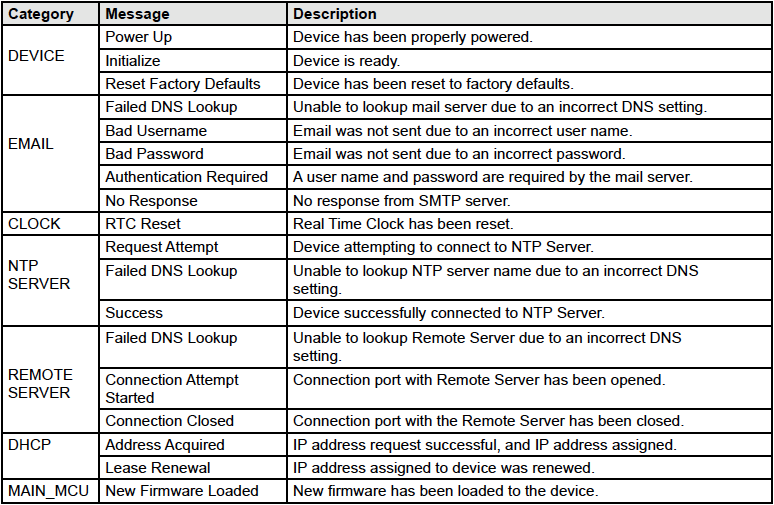
The syslog file records various system events, which can be used for diagnostics and troubleshooting purposes.
File Format:
MM/DD/YYYY HH:MM:SS, (category to which message applies): (message)
Sample File:
01/02/2010 04:08:13 DEVICE: Power Up.
01/01/2010 00:41:05 DEVICE: Reset factory defaults.
Listed below is a description of messages that a user may see:
This file is read by requesting the syslog.txt file. For example, using the default IP address, the following command would be used:
http://192.168.1.2/syslog.txt
Note: The setup username and password are required to access this file.
If the TCP port has been changed (not port 80), the port will be required to read the file. For example,
using the default IP address, and port 8000, the log file would be read as follows:
http://192.168.1.2:8000/syslog.txt
To erase the file, use: http://192.168.1.2/syslog.txt?erase=1
Section 2: Modbus/TCP
2.1 Modbus/TCP (slave)
ControlByWeb modules can be controlled and monitored using Modbus/TCP protocol. This provides a standard means of using the module with devices and software from other manufacturers. This section is not a tutorial on Modbus and it is assumed that the reader is already familiar with Modbus. Detailed Modbus information can be found at http://www.modbus.org.
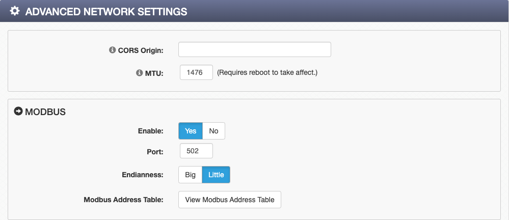
Note: Modbus communications are disabled whenever the User account is enabled. This is because Modbus/TCP does not provide a mechanism for password protection. Make sure the User account is disabled (default) and Modbus functionality is enabled on the Advanced Network.
The module functions as a Modbus slave. Host devices, such as PLCs, open a connection with the module on port 502 (configurable under Advanced Network tab) and then send requests to read or set I/O states, or sensor values. When the module receives a command, it performs the desired function and returns a response.
The module can have additional I/O added and removed that can cause changes to the Modbus address map. For an up-to-date map of I/O on the module to the addresses for Modbus, please select the View Modbus Address Table button from the Setup pages under the Advanced Network tab.
The Modbus Address Table will list all the addresses to be used when accessing I/O on the module. It is broken down into three groups: register addresses, coil addresses, and discrete input addresses. Register addresses are used with the Modbus register functions. Coil addresses are used with the Modbus coil functions, and discrete input addresses are used with Modbus discrete input functions.
The following is an example of a Modbus Address Table. Note that while the module might not have all the I/O hardware present in the table, it can have remote I/O for those types.
This section includes:
- Modbus Function Codes and Examples
- Reading/Writing Registers and Coils & Reading Discrete Inputs
- PLC Device Addressing & Examples
The first column in the Modbus Address Table lists the name of the I/O. The seconds column lists the register address for the I/O. All I/O can be read and written as a register using this address and the modbus register functions regardless of the I/O type. Columns 3 through 6 are the register addresses used to access auxiliary functions of relays that have Pulse Timers, and digital inputs that have Counters, On Timers, and Total On Timers. The seventh column contains addresses used to read and write digital I/O and relays using the modbus coil functions. The last column contains addresses used to read digital I/O and inputs using the modbus discrete input functions.
2.1.1 Modbus Function Code Summary
The module supports the following function codes for reading and writing I/O. If the I/O type does not exist on the module, the function code is still supported for use with remote I/O of that type.
| Code Name | Modbus Function | Usage |
| Read Coils | 01 | Read Relays and Digital I/O (Configured as outputs) |
| Read Discrete Inputs | 02 | Read Digital Inputs and Digital I/O (Configured as inputs) |
| Read Multiple Registers | 03 | Read Vin, Sensors, Registers, Counters, Analog Inputs (All I/O both Local and Remote) |
| Write Single Coil | 05 | Write Relays and Digital I/O (Configured as outputs) |
| Write Multiple Coils | 15 | Write Digital Inputs and Digital I/O (Configured as outputs) |
| Write Multiple Registers | 16 | Write Digital I/O Pulse Counters, Registers, Counters (All writable I/O) |
Multiple commands may be sent without closing and re-opening the connection, but if no data is transferred for 50 seconds, the connection will time out and close. To keep the connection open, a read request can be sent periodically.
The module has two TCP sockets available for Modbus/TCP. This allows two connections to be open at one time. Requests for more than two open connections will be rejected.
When errors occur, an error code is returned. Most Modbus client software will interpret this code in a human readable form. The code is comprised of the original function code plus 0x80. For example, an error during the read coils function 0x01 would return 0x81. Each error has a qualifying exception number. The following are the possible exception codes and their meanings:
0x01 – Function code not supported (also when Modbus is disabled in the setup pages).
0x02 – Incorrect starting address/quantity of output combination.
2.1.2 PLC Device Addressing
There are generally two schemes for accessing Modbus devices. The first is by specifying the Modbus function code, memory type, and address. The second and more modern option, sometimes called PLC addressing, requires only the address.
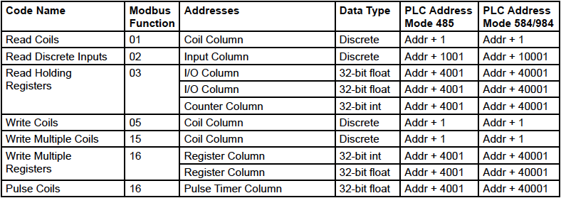
Modbus protocol uses four different address ranges for discrete inputs, coils, input registers, and holding registers. The function code determines the address range of the message. The following are common function codes and their respective address ranges.
| Code | Modbus Function | Data Type* | PLC Address Mode 485 | PLC Address Mode 584/984 |
| Coils (Read/Write) | 01, 05, 15 | Discrete | 1-1000 | 1-10000 |
| Discrete Inputs (Read only) | 02 | Discrete | 1001-2000 | 10001-20000 |
| Holding Registers (Read/Write) | 03, 06, 16 | 8-64 bits | 4001-5000 | 40001-50000 |
*Data types may be implemented at the discretion of the manufacturer. Address ranges may also overlap. Discrete is a binary or boolean value, 1 or 0.
Function codes, memory types, and addresses can be converted to the PLC addressing equivalent using the table below. To use the table, look up the row corresponding to the Modbus function code. Then take the desired ControlByWeb device feature address and add to it the address offset in the PLC address mode column.
Input Address + PLC Base Address = PLC Address
For example, to read Relay 1
Relay Address 1
PLC Base address 10001
PLC Address 10002
Programming the PLC to read from 10002 will return the value of Relay 1.
2.1.3 PLC Addressing Examples
The following tables provide you with the information needed to read a PLC address.
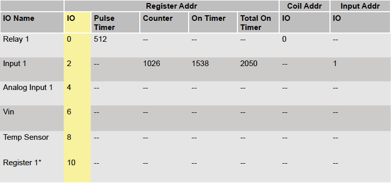
Example Modbus Address Table
*This refers to the Register I/O within the unit, and not the Modbus registers.
The appropriate function code/address and PLC equivalent addresses are shown below. Please keep in mind that Modbus addressing may start at 0 or 1 (depending on various manufacturers). Typically Function code addressing starts at 0, and PLC addressing starts at 1.
All addressing is obtained from the Example Modbus table. Use either the function code and address or the PLC address, whichever is required by your PLC/software.
Read relay 1:
Function code 0x01, address 0
PLC address 1
Write relay1:
Function code 0x05 or 0x015 (for multiple relays), address 0
PLC address 1
Pulse Relay 1, written as a 32 bit float (pulse duration in seconds)
Function code 0x16, address 512 – 513
PLC address 40513 – 40514
Read Input1 (Digital input1)
Function code 0x02, address 1
PLC address 10002
Read Holding registers:
• Analog input1
– Function code 0x03, address 4 – 5, 32 bit float
– PLC address 40005 – 40006, 32 bit float
• VIN
– Function code 0x03, address 6 – 7, 32 bit float
– PLC address 40007 – 40008, 32 bit float
• Temperature sensor
– Function code 0x03, address 8 – 9, 32 bit float
– PLC address 40009 – 40010, 32 bit float
• Internal Register (Register value within the Series 4 unit, an I/O type not to be confused with Modbus registers).
– Function code 0x03, address 10 – 11 32 bit float
– PLC address 40011 – 40012, 32 bit float
– Write using Function code 0x16, with the same address.
2.1.4 Read Coils – Modbus Function Code 01 (0x01)
Read the state of relays and digital I/O configured as outputs.
Request
Start Address: Refer to Modbus map in setup pages
Coil Quantity: Refer to Modbus map in setup pages. Multiple Outputs may be read at the same time by specifying the correct starting address and quantity of coils to be read.
Response
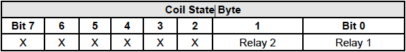
The module will respond to the request with a data field of one or more bytes depending on the number of coils read. Each bit represents a coil status. A ‘1’ indicates the Output is ON. A ‘0’ indicates that the Output is OFF.
Bit zero of the return value will be the state of the coil corresponding to the start address. For example, if a start address of 0x0001 is used, bit zero will be the status of the first relay or digital I/O.
Errors
The sum of the start address and coil count cannot exceed the maximum coil count or an error response will be returned.
The following are possible error responses:
| Coil Read Error Function Code (1 byte): | 0x81 |
| Exception Codes (1 byte): | 0x01 – Function code not supported. 0x02 – Incorrect combination of start address and quantity of Relays |
2.1.5 Read Discrete Inputs – Modbus Function Code 02 (0x02)
This function returns the state of digital inputs and digital I/O (when configured as inputs).
Request
Start Address: Refer to Modbus map in setup pages
Input Quantity: Refer to Modbus map in setup pages. Multiple Inputs may be read at the same time by specifying the correct starting address and quantity of inputs to be read.
Response
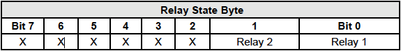
The inputs states are indicated by bits in the status byte(s). A 1 indicates that the input is switched ON. A 0 indicates that the input switched OFF. Bit zero of the return value will be the state of the discrete input corresponding to the start address. For example, if a start address of 0x0001 is used, bit zero will be the status of input 2.

Errors
| Input Read Error Function Code (1 Byte): | 0x82 |
| Exception Codes (1 byte): | 0x01 – Function not supported. 0x02 – Incorrect combination of start address and quantity |
2.1.6 Read Holding Registers – Modbus Function Code 03 (0x03)
The Read Holding Registers function is used mainly to read analog I/O such as the analog inputs, registers, counters, and vin. All I/O can be read using this function code. The holding register addresses can be found in the Modbus Address Table in the Advanced Network setup page under Modbus.
Request
32-bit sensor values are read from 16-bit register pairs. Consequently, senors addresses and registers must be read in pairs of 2.
Start Address: Refer to Modbus map in setup pages
Input Quantity: Refer to Modbus map in setup pages. Multiple Registers may be read at the same time by specifying the correct starting address and quantity of registers to be read. The number of registers read must be divisible by 2. For example, if you are reading 4 sequential temperature values, then you must read 8 sequential Modbus register values.
Response
32-bit floating-point values are returned, either as little-endian or big-endian numbers, depending on the configuration in the Advanced Network tab. The floating point values are converted using IEEE 754 floating point value conversion.
With little-endian ordering, a temperature reading of sensor 1 would return 0x800042A2. The least significant word would be 8000 hex and the most significant word would be 42A2. This hexadecimal value converts to a temperature reading of 81.25 degrees.
If a temperature or humidity sensor is not installed, a value of 0xFFFFFFFF (NaN) is returned. Other inputs will show measured values of the open circuits.
Errors
| Sensor Read Error Function Code (1 byte): | 0x83 |
| Exception Codes (1 byte): | 0x01 – Function code not supported. 0x02 – Incorrect combination of start address and input quantity |
2.1.7 Write Single Coil – Modbus Function Code 05 (0x05)
Control digital outputs and relays one at a time.
Request
Start Address: Refer to Modbus map in setup pages
Output Value: 0x00 (Off), 0xFF(On)
Response
The response mirrors the requested state, 0x00 or 0xFF.
Errors
| Single Coil Write Error Function Code (1 Byte): | 0x85 |
| Exception Codes (1 byte): | 0x01 – Function not supported. 0x02 – Address out of range. 0x03 – Padding value. |
2.1.8 Write Multiple Coils – Modbus Function Code 15 (0x0F)
One or more bytes can be written to set the state of multiple digital outputs and relays, each bit representing one digital output or relay.
Request
Digital output and relay states are controlled by specifying the start address of the first digital output to be controlled, the number of the digital outputs to be affected, and the digital output state byte(s).
A value of 0xFFFF would be used to turn ON up to 16 digital outputs and relays. A value of 0x0000 would be used to turn them OFF. A value of 0xF0 would turn off the first 4 digital outputs while turning on outputs 5 through 8.
| Start Address (2 bytes): | Refer to Modbus map in setup pages |
| Output Quantity (1 bytes): | Refer to Modbus map in setup pages |
| Byte Count (1 byte): | Refer to Modbus map in setup pages (Output Quantity divided by 8) |
| Digital I/O Value (Byte Count bytes): | 0x0000 – 0xFFFF |
Response
The quantity value is returned.
Errors
| Multiple Coil Write Error Function Code (1 Byte): | 0x8F |
| Exception Codes (1 byte): | 0x01 – Function not supported 0x02 – Incorrect combination of start address and Digital I/O quantity 0x03 – Byte count out of range |
2.1.9 Write Multiple Registers – Modbus Function Code 16 (0x10)
The Modbus Write Multiple Registers function can be used to set the state of writable analog I/O such as registers and analog outputs.
Request
Start Address: Refer to Modbus map in setup pages
Input Quantity: Refer to Modbus map in setup pages. Multiple Registers may be written at the same time by specifying the correct starting address and quantity of registers to be read. The number of registers written must be divisible by 2. The values sent are in IEEE 754 floating point format. Also, the endianness configured in the Modbus setup pages is taken into account.
In little-endian the value 81.25 would be as follows: 0x800042A2. The least significant word would be 8000 hex and the most significant word would be 42A2. In big-endian, the least significant word would be 0x42A2 and the most significant word would be 0x8000.
Response
The request is acknowledged by responding with the register quantity that was written.
Errors
| Pulse Function code Error (1 Byte): | 0x90 |
| Exception Codes (1 byte): | 0x01 – Feature not supported. 0x02 – Address quantity not an even number. Incorrect combination of start address and register count. |
Section 3: SNMP Requests
3.1 SNMP Requests, Objects and Community Strings
All configured I/O and some simple network parameters can be retrieved using Simple Network Management Protocol (SNMP). For most cases, using SNMP is as simple as locating the appropriate Management Information Bases (MIB) files and loading them into the SNMP manager software. The module will generate an MIB file, based on its current I/O configuration, for use with the SNMP manager software. If any I/O are configured (added/ deleted), a new MIB will need to be generated.
Additional information on SNMP can be found at http://www.net-snmp.org/
The 400 Series supports SNMP V1, V2c, and V3. Any SNMP version can be selected and used.
SNMP is configured under the Advanced Network setup tab. See Section General Settings Tab > ADVANCED NETWORK SETTINGS for more information.
The module supports the following Packet Data Units (PDU):
- GetRequest
- GetNextRequest
- GetBulkRequest
- SetRequest
- Trap
- Notification
This section includes:
- Standard & Module Objects
- Traps
- Notifications
- Community Strings
- SNMP V3 User-Based Security Model
3.1.1 Standard Objects
The module supports several standard RFC1213 objects that usually come with SNMP management software. If not, an Internet search for RFC1213-MIB will turn up multiple links.
| RFC1213 Object | Response |
| system.sysDescr | X-4xx |
| system.sysObjectID | X4xx |
| system.sysUpTime | Time in hundredths of seconds since the device was last powered. |
| system.sysName | X-4xx* |
3.1.2 Module Objects
All configured I/O on the module can be monitored and controlled through SNMP. The MIB file can be generated for the module by going to General Settings Tab > ADVANCED NETWORK SETTINGS and pressing the button Generate and Download MIB File. This file should be regenerated whenever there are changes made to the I/O.
3.1.3 TRAPS
Send SNMP traps when a relay changes state, when a particular sensor value is reached, or when the supply voltage is out of the desired range. Traps are configured as actions in Conditional and Scheduled tasks. As more I/O are added to the module, more I/O will appear in the MIB file.
3.1.4 Notifications
Supports sending of SNMP Notifications when the SNMP version is 2c or 3. Notifications are similar to traps except they require a response to be sent back from the SNMP manager. Retries will occur if the SNMP manager does not return a response. This makes notifications more reliable than traps. Notifications are configured as actions in Conditional and Scheduled tasks.
3.1.5 Community Strings
The module allows customization of both the read and write community strings. The proper community string will be needed for all read and write requests. By default both read and write community strings are webrelay. Community strings are only used by SNMP versions 1 and 2c. SNMP version 3 uses a different security mechanism.
3.1.6 SNMP V3 User-Based Security Model
The module supports the SNMP V3 User-Based Security Model (USM). This replaces the community strings “security” of SNMP V1 and 2C. The details of USM can be complicated, but the main thing is that both the module’s security settings and the SNMP Manager’s security settings need to match for it to work.
There are two protocols used for USM. The first, authentication protocol, allows the SNMP manager to authenticate the module and vice versa. The second, privacy protocol, allows the SNMP communication to be encrypted. Each protocol has an “algorithm” and a password associated with it. There is also a security username that is shared by both protocols.

Section 4: MQTT Functionality
4.1 MQTT and Sparkplug B
The 400 Series ControlByWeb modules have the ability to communicate via MQTT and Sparkplug B. These devices currently support MQTT version 3.1.1 The following section briefly describes the MQTT protocol and how it can be used to control and monitor I/O.
The MQTT tab is found at the bottom of the General Settings tab.
Additional information on MQTT and Sparkplug B can be found at https://www.hivemq.com/mqtt/
To integrate your ControlByWeb device with ThingsBoard, click here for an additional help document.
To use connect your ControlByWeb device to the open source MQTT broker Mosquitto, click here for an additional help document.
This section includes:
- Establishing a Broker
- Subscribing
- Publishing
- Sparkplug B
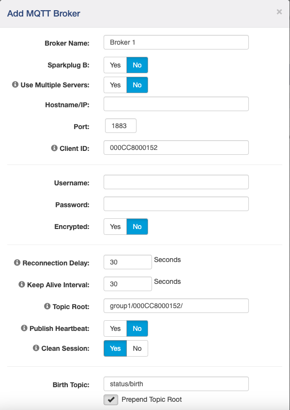
4.1.1 Establishing an MQTT Broker
An MQTT broker is a server that allows MQTT clients to communicate by receiving messages, filtering them by topic, and distributing them to subscribers. The ControlByWeb device allows you to use multiple servers as a backup fail over in case the main server is not available.
Once a broker has been established, the device will use the provided broker for all communication and distribution to subscribers. All configured I/O can be monitored and controlled through MQTT.
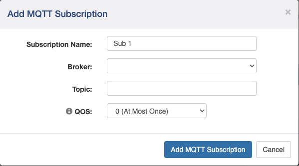
4.1.2 Subscribing to a Broker
ControlByWeb devices send a subscribe to the broker defined in the Broker tab. A device that is subscribed to a certain broker will receive the I/O information that has been previously published by another device. Receive information whenever an I/O changes state or is updated by a device the ControlByWeb device is subscribed to.
4.1.3 Publishing to a Broker
ControlByWeb devices send a publish to the broker defined in the Broker tab. A device that publishes to a certain broker will send the I/O information to a broker to be accessed by another device. Send information to the broker whenever an I/O changes state or is updated by a ControlByWeb device. Subscribed devices can receive this information to monitor and control I/O.
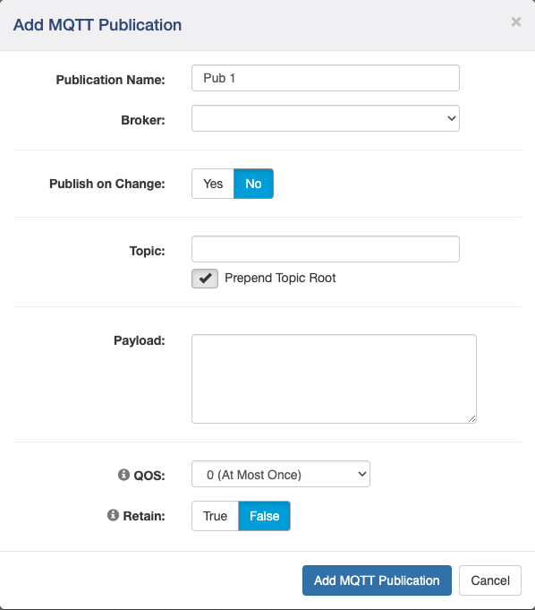
4.1.4 MQTT Payload Tokens
| I/O Name / System Variable | MQTT Payload Token |
| MAC Address | ${mac} |
| Firmware Revision | ${ver} |
| Serial Number | ${ser} |
| Up Time | ${uptime} |
| IP Address | ${ip} |
| HTTP Port | ${port} |
| HTTPS Port | ${httpsport} |
| Epoch Time Stamp | ${dateTime} |
| Name (Control Page Header) | ${name} |
| Model Number | ${model} |
| ClientID | ${clientID} |
| Digital Input 1 | ${digitalInput1} |
| Digital Input 2 | ${digitalInput2} |
| Digital Input 3 | ${digitalInput3} |
| Digital Input 4 | ${digitalInput4} |
| Relay 1 | ${relay1} |
| Relay 2 | ${relay2} |
| Relay 3 | ${relay3} |
| Relay 4 | ${relay4} |
| Vin | ${vin} |
| Register 1 | ${register1} |
4.1.5 Using Sparkplug B
Sparkplug B is an alternative protocol to typical MQTT. Sparkplug B functions similarly to standard MQTT with defined structure for naming topics and format for structuring payloads.
Additional information on Sparkplug B can be found at https://www.hivemq.com/mqtt/mqtt-sparkplug-essentials/
Section 5: External Servers and Remote Services
5.1 External Server and Remote Services
External servers can be used to access ControlByWeb devices. Within the on-board firmware of each device, Remote Services can be enabled which allows access from external servers. By using an external web server, multiple ControlByWeb devices can be integrated into a single control page.
Note: The following methods are supported by the module; however, Xytronix Research & Design, Inc. does not provide or support custom third-party applications, or external web servers.
This section includes:
- Using custom/third party software to access the module
- Using an external web server
- Remote Services
5.1.1 Accessing the module with custom software or third-party applications
Custom applications can send commands to the module for monitoring and control functions using HTTP requests for XML or JSON files. (See Section XML and JSON for more information) The application interface can be used to provide a custom user interface, access to multiple units in a single screen, and allow for automation, logging, and other application-specific features.
5.1.2 Using an External Web Server
Rather than accessing the module directly from a computer, an external web server can be used. The term “external” web server is used here to mean a separate web server (such as Apache, IIS, or NGINX) that is not the web server built into the module. In this scenario, users access custom web pages that reside on the external web server and the external web server communicates with the module.
An external web server can integrate multiple ControlByWeb devices into a single control page. In other words, the user may not be aware that he/she is using multiple ControlByWeb™ devices, but rather the user sees an integrated control page for the entire system. In addition, the use of an external web server allows programmers to create custom user interfaces that take advantage of the additional resources typically available on larger web servers, including more memory and various web programming languages.
There are two approaches that an external server can use to communicate with the module and other ControlByWeb™ devices: Direct Server Control, and Remote Services.
Direct Server Control
The first approach is for the external server to create a TCP connection whenever it needs to access the ControlByWeb device. In this case, the external server opens the connection, sends commands and/or reads the device, and closes the connection.
This method is ideal when the web server and all of the ControlByWeb devices are on the same network (without routers between them). In this case, the server can communicate with the devices directly and securely since data never has to leave the local network.
When the server and the ControlByWeb devices are on different networks, routers must be configured to allow appropriate access. If a public network is used, such as the Internet, security precautions should be considered.
Remote Services
The second approach is for the ControlByWeb device to initiate a connection using Remote Services. The settings under the Advanced Network tab in the setup pages will enable the device to open a TCP V1 connection with an external server. Once the connection is open, the external server can send commands and/or read the device. The external server can leave the connection open (so that it never closes) or close the connection.
Remote Services is ideal for installations where the server and the device are installed on different networks. This is especially useful when each device is installed on a separate private network. For example, if the user doesn’t control the network connections where the ControlByWeb device is installed, Remote Services would initiate a TCP connection over the Internet with the control computer. Since the ControlByWeb device initiates the connection, the control computer doesn’t have to know the IP address of the device. This means that the device can be installed using DHCP. In addition, no special router configuration is required. This makes the network installation of the device very simple, and since no incoming ports need to be opened in the router, security is not compromised. See Section General Settings Tab > ADVANCED NETWORK SETTINGS for more information.
The ControlByWeb device can be configured to establish a connection when triggered by an event, such as an I/O state changing. This is done by setting a conditional task with the action being Send Device State to Remote Service.
With Remote Services enabled, a connection attempt will be made periodically according to the Connection Interval setting in the Advanced Network setup tab. The Connection String consists of static information about the device, a user-defined character string configured in the Advanced Network tab and ends with sending the state.xml.
The connection string is also sent at the same interval once the connection is open. The external server is responsible for closing the connection when it is done.
A three-character “ACK” response is expected in return to every connection string. If the “ACK” is not received within 10 seconds, the ControlByWeb device will close the connection.
When a logic event occurs and an action of send state is sent to a remote server and a connection is open, the state.xml file is sent.
Note: Version 2.0 is reserved for ControlByWeb.Cloud and is not designed for any other use.

Section 6: ControlByWeb Cloud
6.1 Cloud API
ControlByWeb devices can connect to the optional ControlByWeb Cloud for remote user access, a central login for all cloud connected devices, and for cloud-based data logging. The ControlByWeb Cloud API lets you create DAT URLs, that when used with HTTP Get commands enables another option for integrating with our devices.
Additional information about the ControlByWeb Cloud API can be found at https://docs.controlbyweb.cloud/
This section includes:
- Accessing and using DAT URLs in the ControlByWeb Cloud
6.1.1 Accessing DAT URLs in ControlByWeb.Cloud
Your ControlByWeb device can be accessed through the ControlByWeb Cloud at http://www.ControlByWeb.Cloud after entering your login information.
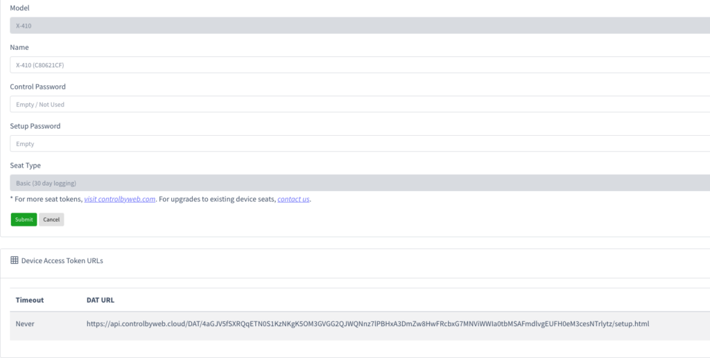
A DAT URL can be manually generated or generated through our Cloud API. Information on adding a device access token can be found at https://docs.controlbyweb.cloud/api/devices.html#get-device-access-token
The following steps explain how to manually generate a new DAT URL in the ControlByWeb Cloud:
- On the left side of your browser, click on Devices.
- Then, click the edit button on the right-hand side of the device you wish to edit.
- In the bottom right of the screen, click the green New DAT URL button.
- Enter the number of minutes you want the DAT URL to be valid for. Enter “0” if you want it to last forever.
- Click the green Submit button and DAT URL will be created.
6.1.2 Using DAT URLs
With the ControlByWeb Cloud, you can use DAT URLs to communicate with other ControlByWeb devices without port forwarding.
To view the current state of the device visit the URL with /state.json or /state.xml at the end. For example:
https://api.controlbyweb.cloud/{generated DAT url}/state.json
The following is an example of how the DAT URLs can be used in conjunction with XML/JSON to trigger either 1 or multiple relays from anywhere in the world without the need for port forwarding:
https://api.controlbyweb.cloud/{generated DAT url}/state.json?relay1=1&relay2=1
This command triggers Relay 1 and Relay 2 in a single command line:
state.json?relay1=1&relay2=1
Note: While DAT URLs will facilitate 3rd party integration with our devices, they do not facilitate peer-to-peer communication between ControlByWeb devices. For more information on inter-device peer-to-peer communication, see the 400 Series User’s Manual.