
Section 2: Installation and Connections
Installation consists of mounting the device, connecting it to an Ethernet network, connecting the I/O to other accessories/sensors, and providing power. The installation is completed by configuring the device’s settings using a web browser.
2.1 Installation Guidelines
- This device must be installed by qualified personnel.
- This device must not be installed in unprotected outdoor locations. This device should be located in a clean, dry location where it is protected from the elements. Ventilation is recommended for installations where ambient air temperatures are expected to be high.
- This device must not be used for medical, life-saving purposes, or for any purpose where its failure could cause serious injury or the loss of life.
- This device must not be used in any way where its function or failure could cause significant loss or property damage.
- Do not use to directly control motors or other actuators not equipped with limit switches or other safeguards to protect from equipment or wiring failures.
- If this device is used in a manner not specified by ControlByWeb, the protection provided by the equipment may be impaired.
- CAUTION: Miswiring or misconfiguration could cause permanent damage to the device, the equipment to which it is connected, or both.
- CAUTION: Make sure the power is shut off before making connections
Wall Mounting
Mount the module to a wall by using two #8 screws. Attach the screws to the wall vertically spaced exactly 2.5 inches apart. The head of the screw should be about 1/10 inch away from the wall.
DIN-Rail Mounting
The module can be mounted to a standard (35mm by 7.55mm) DIN-Rail. Attach the module to the DIN-Rail by hooking the top hook on the back of the enclosure to the DIN-Rail and then snap the bottom hook into place. To remove the from the DIN-Rail, use a flat-head screwdriver. Insert the screw driver into the notch in the release tab and pry against the enclosure to release the bottom hook.
2.2 Power Supply Connections
A removable terminal connector is provided for making the power connections. To help protect the module from mechanical stress:
- Make sure power is turned off and
- Remove the terminal connector from the module and make wiring connections to the terminals.
- Reconnect the terminal connector and apply power.
See Appendix D: Specifications for wire size, temperature rating, and torque requirements for making connections to the terminal blocks.
2.2.1 Power Supply and Power-Over-Ethernet Connections
The X-4xx unit requires power for its internal logic circuits. Connect a 9-28 VDC power supply to the +Vin and Gnd terminals. A regulated power supply is recommended, such as a wall-mount AC-DC adapter. Verify that the adapter is rated for the operating current of the X-4xx (See Appendix D: Specifications for the current requirements.)
Multiple modules and other devices may be connected to a single power supply by connecting the power supply input terminals in parallel. The power supply must have an ample current rating to power all units connected.
POE models (X-4xx-E) are normally powered from a Power Sourcing Equipment (PSE) device which passes DC power along with data on the twisted pair Ethernet cabling. This allows a single cable to provide both the data connection and DC power. With the X-4xx-E no connections are needed to the Vin+ and Gnd terminals. The Vin+ and Gnd terminals however, can be used as a backup power source. The X-4xx-E has an internal “diode or” circuit between the Vin+ terminal and the internal Powered Device (PD) circuits. If a power supply is connected to the Vin+ terminal, the X-4xx-E will draw power from the PSE if the input voltage is less than 12.0V, and from the Vin+ terminal if the input voltage is greater than 12.0V. If the PSE power fails, the X-4xx-E will draw all power from the Vin+ terminal.
2.2.2 Notes about powering the X-400 (X-400 only)
The expansion modules draw their power from the X-400 through the expansion bus ribbon cable. If expansion modules are connected to the X-400, the power supply must have enough capacity to power both the X-400 and any expansion modules connected to the X-400. The expansion bus can provide up to 1.70 Amps for powering the attached expansion modules. The maximum number of expansion modules you can attach depends on the module type and power requirements of the modules. The expansion modules employ modern switch-mode power supplies. With this type of power supply, the current draw decreases as the voltage increases. As such, you can add more expansion modules by using a 24-volt power supply than you can with a 12-volt power supply. If additional power is needed for modules on the expansion bus, please see the next section called Optional Power Injector (X-400 only).
As an example, an X-11s (2 relay expansion module) would use 105 mA with a 24VDC power supply when connected to the X-400. The X-400 would be able to support up to 16 modules under this configuration (16 X 105mA = 1.68A). This example is workable because the expansion bus load current is less than 1.70 Amps. For this example, the power supply must be capable of providing 1.76A at 24VDC (80mA for the X-400 plus 1.68A for the devices on the expansion bus).
If only using a 12VDC power supply, each X-11s (2 relay expansion module) would use 196mA. The X-400 would be able to support eight modules under this configuration (8 x 196mA = 1.57A). This configuration is workable because the expansion bus load current is less than 1.70 Amps. For this example, the power supply must be capable of providing 1.72A at 12VDC (150mA for the X-400 plus 1.57A for the devices on the expansion bus).
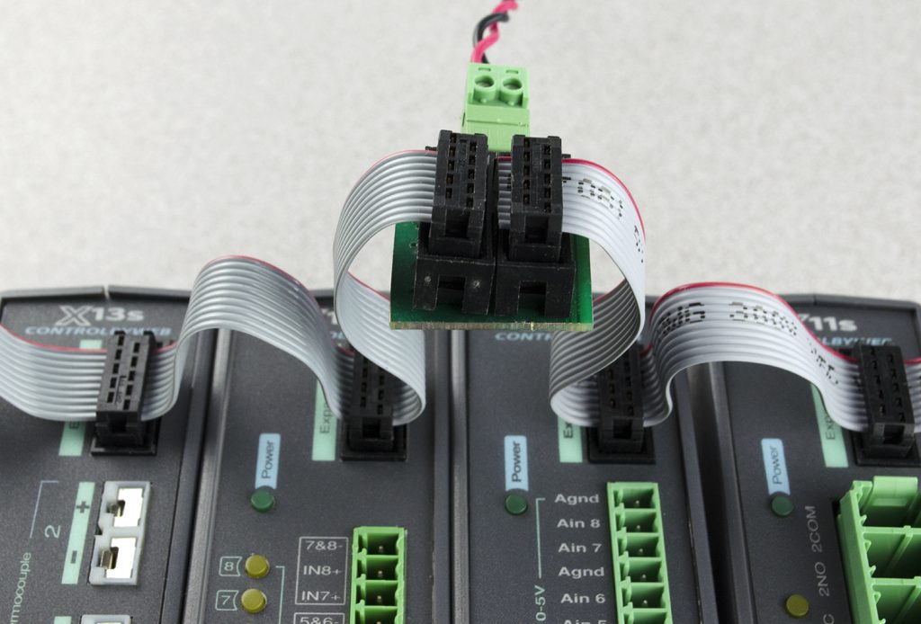
2.2.3 Optional Power Injector (X-400 only)
As described in the section above, the expansion modules draw their power from the X-400 through the expansion bus ribbon cable. The X-400 can provide up to 1.7 Amps for powering the attached expansion modules. In applications where a large number of expansion modules are used and additional current capacity is needed, a DC power injector can be employed. This accessory has two ribbon cable connectors and a connector for supplying power (9-28V DC) to the expansion bus separately from the X-400. The communication signals pass through the power injector, but the DC power from the X-400 does not. The power injector thus provides power for all of the expansion modules to the left side of the injector. The ribbon cable itself can only carry 1.7Amps maximum. Install one or more power injectors such that no portion of the ribbon cable carries more than 1.7Amps.
Note: To provide a coordinated power-up sequence, it is recommended to power the X-400 and any power injectors using the same power supply.
2.2.4 Notes about powering the X-404 (X-404 only)
Modbus sensors draw their power from the X-404 through the RS-485 5 pin connector. If modbus sensors are connected to the X-404, the power supply must have enough capacity to power both the X-404 and any modbus sensors connected to the X-404. The RS-485 bus can provide up to 1.70 Amps for powering the attached Modbus sensors. The maximum number of Modbus sensors you can attach depends on the power requirements of the sensors, up to a maximum of 32 sensors.
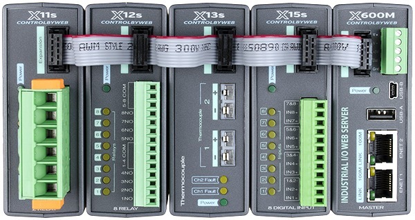
2.3 Expansion Module Connections (X-400 only)
Expansion modules are connected to the X-400 with a 10-conductor ribbon cable. Normally the X-400 and the expansion modules are mounted side by side as shown in the photo below. The ribbon cable connectors have a polarization lug to ensure correct connections.
Note: The following image shows the X-600M connected to several expansion modules; however, connecting expansion modules to the X-400 is the same.
2.4 RS-485 Connections (X-404 only)
The X-404 serves as a Modbus Master device. The D(A) and D(B) terminals provide serial RS-485 communications. RS-485 is used to implement linear bus topologies using only two wires. It is recommended to arrange the bus as a connected series of multi-drop nodes in a line or bus, not a star or ring. Star or ring topologies are not recommended because of signal reflections. In addition to the differential pair signals, you must make a ground connection between the shield or power supply common of your Modbus slave devices and one of the GND terminals on the X-404. The signal common (SC) ground connection serves to keep the D(A) and D(B) signals within the common mode range of the internal RS-485 transceiver.
2.4.1 RS-485 Line Polarization
The X-404 has an internal 120-ohm balanced line termination network. As a master device, the termination network provides pull-up/pull-down bias to insure that its receiver stays in the idle state when no data signal is present. The D(A) circuit has a pull-up resistor to 3.3V volts and the D(B) circuit has a pull-down resistor to Gnd.
Unfortunately, despite the TIA-485 and Modbus over Serial Line Specifications, there is confusion in the industry over the designation of the D(A) and D(B) differential signal connections. The X-404 uses the following connections:
X-404 line polarization
- For a MARK (idle bus), (logic 1), the D(A) terminal is positive relative to the D(B) terminal.
- For a SPACE (logic 0), the D(A) terminal is negative relative to the D(B) terminal
2.5 Cellular Antenna Connector (Cellular Devices only)
Modules that include cellular connectivity come with an omnidirectional antenna for use with the embedded LTE-M cellular radio. The included antenna is suitable for most applications and connects to the female SMA connector on the faceplate. Do not operate these modules without the antenna connected.
The omnidirectional antenna radiates RF signals in all directions in one plane with a pattern shaped somewhat like a doughnut or torus. The radiated power decreases above or below the plane, dropping to zero on the antenna’s axis. Orient the antenna vertically so the antenna will radiate in all horizontal directions and so little radio energy is aimed into the sky or down toward the earth and lost.
The antenna used for this transmitter must be installed to provide a separation distance of at least 20 cm (approx. 8 in) from the device and must not be co-located or operating in conjunction with any other antenna or transmitter except by FCC multi-transmitter product guidelines.
In applications where the included antenna is not optimal, the FCC allows the use of another antenna provided the combined gain of the antenna and cabling is below the limits listed below.
- 3.67 dBi in 700 MHz, i.e. LTE FDD-12 band
- 6.74 dBi in 1700 MHz, i.e. LTE FDD-4 band
- 7.12 dBi in 1900 MHz, i.e. LTE FDD-2 band
2.6 1-Wire Bus Connections
Many modules in the 400 Series have a 1-Wire Bus. This port, which supports up to 16 digital sensors for measuring temperature, humidity, and more. (Note that the X-406 has four 1-Wire channels, with each channel supporting up to 16 sensors for a total of up to 64 sensors).
The sensors share the same three connections for communications and power (5Vo, Data, and Gnd). Every sensor on the bus is assigned a unique serial number when it is manufactured. That number is used to address the sensor during communication.
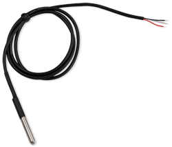
The digital temperature sensors are interchangeable and require no calibration. See Optional Accessories for a list of compatible 1-Wire sensors. Most temperature probes compatible with ControlByWeb modules have a measurement range of -67°F to +257° F (-55° C to +125° C) and an accuracy of +/-0.5 (-10° C to +85° C). A full list of compatible temperature/humidity sensors is listed on our website.
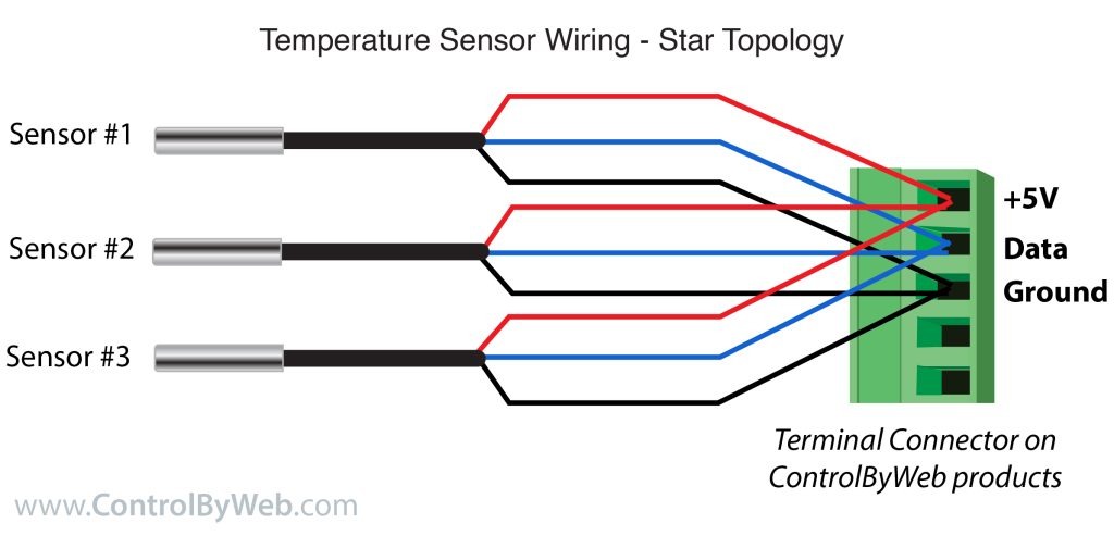
The temperature sensors have three wires as shown below:
| Sensor Wire Color | Connection |
| Red | 5Vo |
| Black | Gnd |
| Blue, White, or Yellow | Data |
2.6.1 Extending Temperature Sensors
Many factors can determine the maximum length of the cable, including the sensor network topology, the type of cable used, the number of sensors, and ambient electromagnetic noise.
Multiple sensors can be connected to the module in two ways: directly connected (star topology) or “daisy chained” (linear topology), as shown below.
Combined cable lengths to all sensors of 600 ft using Cat 5e cable have been successful; however, due to the uniqueness of installation environments, results may vary. Please test in the desired environment before making a permanent installation.
The following are general recommendations that will maximize sensor runs and minimize problems:
- Use small gauge 3-conductor wire (Cat 5e, 18-3 thermostat wire, etc).
- Cat6 wire can be used, but Cat 5 and Cat 5e network cable is recommended, and has proven to be an effective and low-cost solution for long runs. Cat 5e is more tolerant of different wiring configurations.
- Non-shielded works best for longer runs (extra capacitance of shielded wire limits run length).
- The 1-Wire Bus is “single-ended” and has no intrinsic noise protection. It is susceptible to interference if the cable is routed near power lines, fluorescent fixtures, motors or other noise sources. Keep the cable wiring short and avoid routing it near other electrical equipment.
The illustration below shows the recommended connection using Cat 5 network cable. Connect all unused conductors to ground on the module.
A linear (daisy chain) topology will minimize signal reflections, providing a more reliable connection and will allow longer cable length than a star topology.
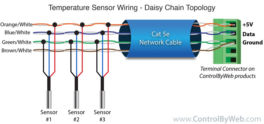
Recommended daisy chain topology connections using Cat5 cable.
2.7 Relay Connections
Relays can be controlled with a web browser, timers, input changes, or programmable logic.
The relays vary in size and configuration. Some modules share common terminal connections between relays (the X-410 for example) with the contacts internally connected together. Some modules have contacts that are completely isolated.
The internal relays can be used to operate indicator lights, interposer relays, and other low-voltage devices.
The screw terminals are internally connected directly to the relays with no internal fuse or other over-current protection.
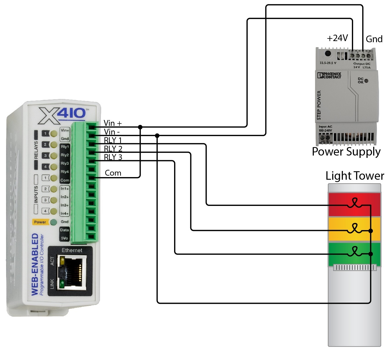
The relay contacts are isolated from all other circuits. The relay contacts may be wired in series with the power source for the load (device to be controlled) as long as the load does not exceed the maximum current and voltage rating of the relay contacts.
When using multiple relays in the X-410, make certain the common for all loads can be connected without causing damage or a short circuit.
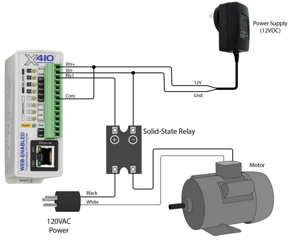
For loads greater than a relay’s specifications, an external interposer relay should be used. The illustration below shows how a 15-Amp motor can be controlled using an external relay. In the example, the X-410’s 1-Amp relay controls the external relay, and the external relay controls the 15-Amp load.
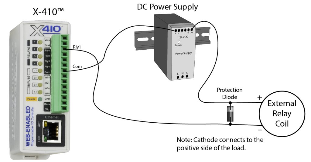
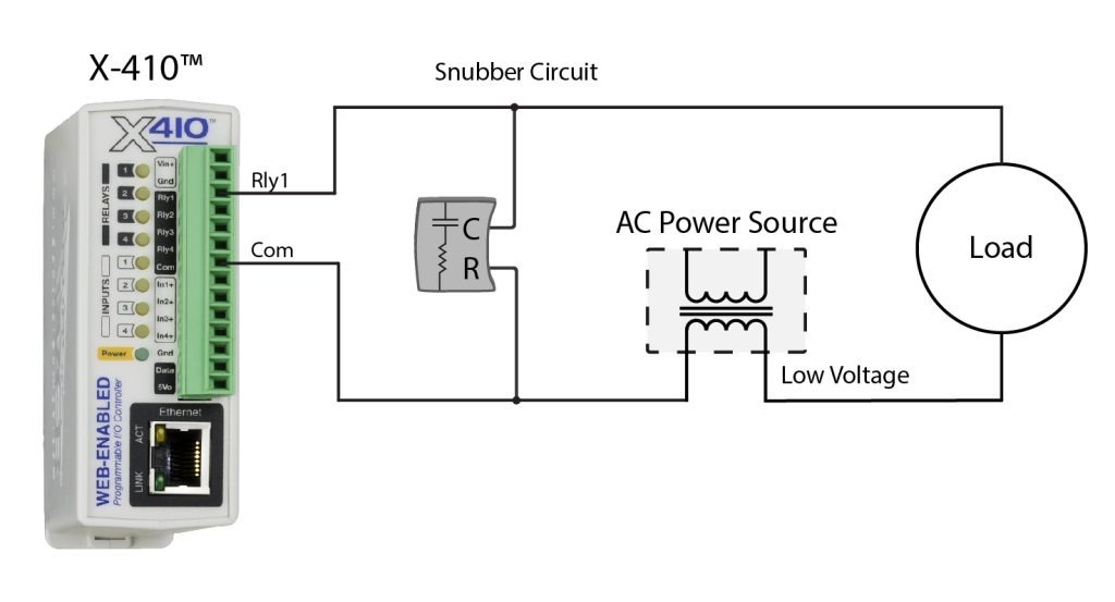
When mechanical relays switch inductive loads such as motors, transformers, electro-mechanical relays, etc., the current will arc across the internal relay contacts each time the contacts open. Over time, this causes wear on the relay contacts which can shorten their life span. When switching an inductive load, it is recommended that relay contact protection devices are used. Note that the modules do not provide relay contact protection in order to provide the greatest versatility and because appropriate protection differs for various loads.
Below is an example of relay contact protection for a DC circuit and an AC circuit. For component values required to provide sufficient contact protection for your application, refer to appropriate references.
2.8 Digital Input Connections
Several of the modules in the have digital inputs. Digital inputs are binary with on/off states where the presence of an input voltage is “on” and the absence of a voltage is “off”. The inputs use photo-coupler circuits to keep internal and external voltages isolated. The digital inputs can be used to control the internal relays, control remote relays (over the network), or simply to monitor the state of a discrete device. To use these inputs, connect a DC control voltage directly to the inputs, and set up the function of the input using the configuration pages. If an AC signal, or a signal greater than the rated input voltage needs to be detected, use a signal conditioner to convert the signal to a DC signal within the input range. With the X-408, the negative inputs of the photo-couplers are paired together with two inputs sharing one screw terminal. With the X-410, the digital inputs are not isolated and share a common ground with the power connection.
DC Input Connections
Each digital input is connected internally through a current-limiting resistor directly to a photo-coupler circuit. No external resistor is necessary as long as the input signal is within the proper range (See Appendix D: Specifications). A DC voltage can be reduced with an external resistor of the appropriate value and power rating to reduce the input current.
The digital input has an internal 3K ohm resistor. The forward voltage drop of the photo-coupler is approximately 1.2V and works well with an input current of 9mA. Use the following formula to determine the resistor value needed for other voltage ranges:
R =((Vin-1.2)/0.009)-3000
Where:
R = External resistor value required
Vin = Desired input voltage
1.2V = forward voltage drop of the LED in the photo-coupler
.009A = workable LED current
3000 ohm = Internal resistor
For example:
To connect a 48VDC signal voltage to the X-410:
R = ((48-1.2)/0.009)-3000 = 2200 ohms
Check the power dissipated by the resistor:
P = I x I x R, The resistor must be at least .009 x .009 x 2200 = 0.18 Watts, so use a 1/2 Watt resistor.
2.8.1 Switch-Closure Connections
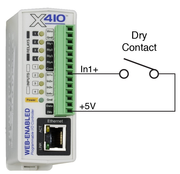
The digital inputs can sense the state of a switch-closure sensor. Sensors with switch-closure outputs include push buttons, magnetic door alarm switches, micro-switches, or any device which has a relay, switch-closure, or open-collector output. The X-4xx modules can be configured for the alarm to be active when the switch is either open or closed.
The illustration below shows an example of using an X-410 to monitor the status of a gate or door over an IP network. The status of the device is detected with a switch. These types of sensors are called “dry contacts” in that the sensor output is a bare switch with no power source. In this example the voltage source for the switch is provided via the +5V output.
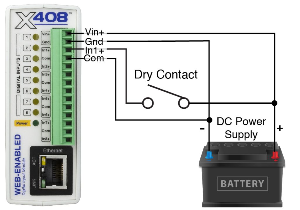
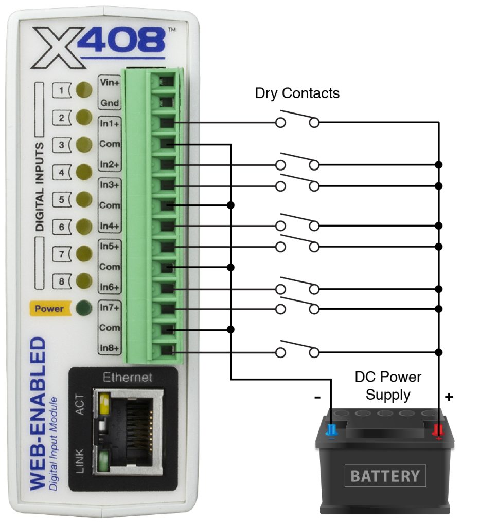
Some modules don’t have a 5V output that can be used to power dry contacts. Additionally, for long wire runs it is better to use a higher voltage like 12V or 24V to compensate for voltage drop across the wires. The illustration below shows how to use the same power supply to power the X-4xx module and the dry contact.
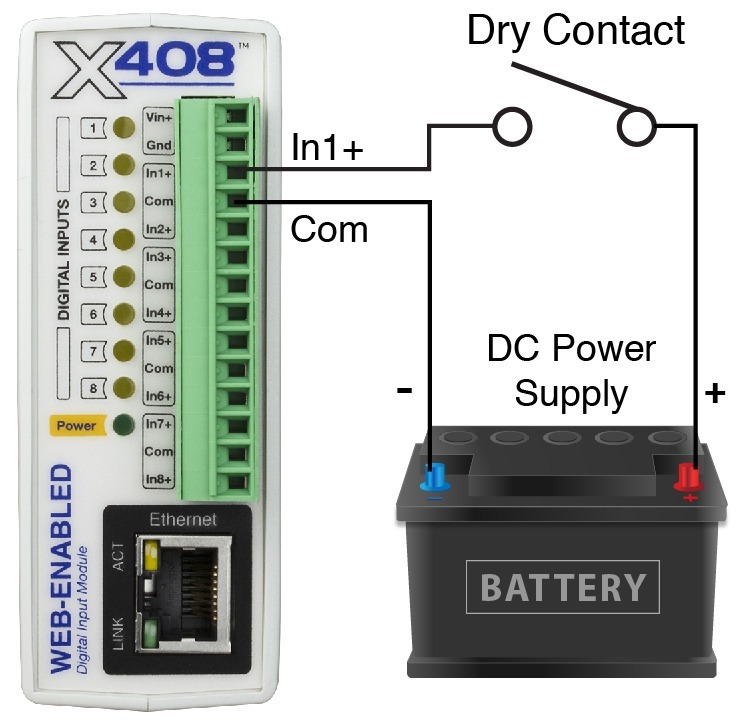
When using modules that are powered using POE (Power Over Ethernet), the 5V output can be used for short wire runs on modules that provide that output. For longer wire runs or for modules that don’t provide the 5V output, a separate power supply will be required to “wet” the contacts as shown below.
Multiple dry contacts can use the same power supply as shown below.
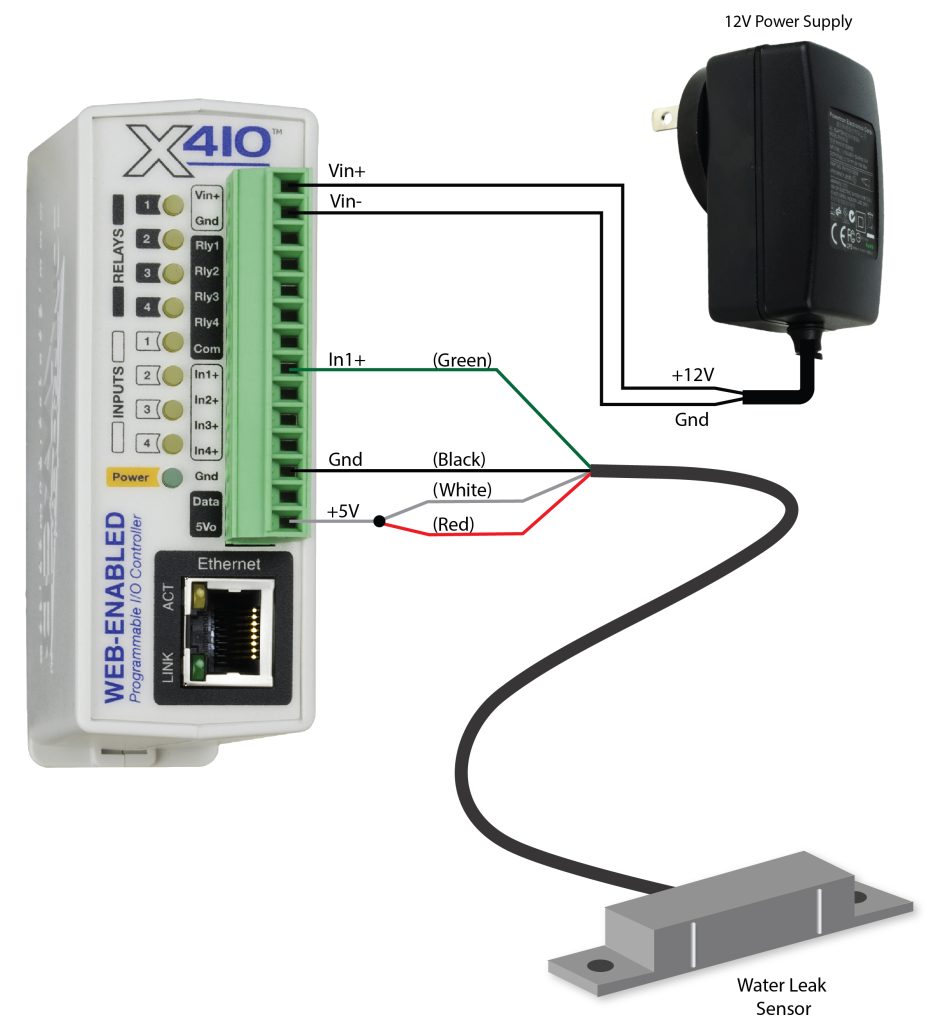
2.8.2 Water Leak Detector Example
A GRI-2605 water leak detector can be directly connected to the module such as an X-408 or an X-410. The sensor detects the presence of water or other conductive liquids. The sensor has 4-wires which are connected as shown below. The GRI-2605 has an internal relay whose contacts (green & white wires) are closed when the sensor is dry. When the sensor is dry the digital input will be “On”. When water is detected, the relay contacts open and the digital input will be “Off”. With the connections shown, the sensor is a supervised alarm circuit such that if a wire is disconnected or the sensor fails, an alarm will be generated. The X-4xx module can be programmed to activate a local relay, activate a relay at a remote location, and send an e-mail warning when a water leak is detected. After installation, test the sensor with a damp sponge or wet towel.
2.8.3 AC Input Connections
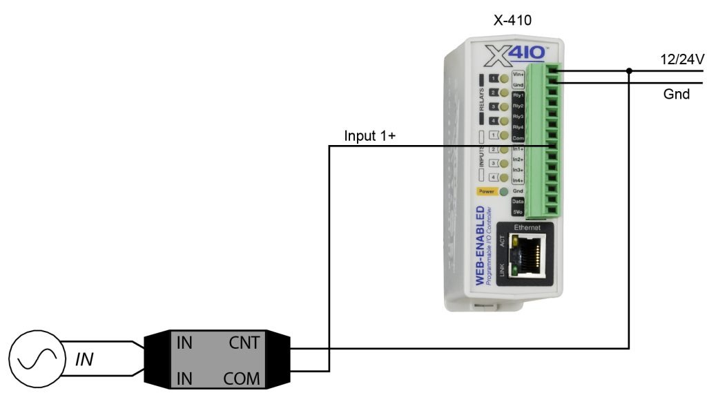
If an AC signal voltage needs to be detected, use a signal conditioner to convert the AC signal to a DC voltage within the input range. An AC signal conditioner can be made using a diode (or bridge rectifier) and a capacitor. Prepackaged signal converters are available as accessories at industrial automation distributors.
A simple voltage converter module (RedLion VCM10000 or VCM20000) is shown below. These are available in two input voltage ranges that cover the range from 4-270VAC/DC. These devices have a MOSFET output (solid state DC contact closure) which is compatible with the X-4xx inputs. The converter module accepts AC (50/60 Hz) or DC voltages with an input pulse rate up to 30 Hz. The converter provides isolation between the input and output using an opto-isolator. You must provide a voltage source for the converter circuit as shown in the example below:
2.9 Analog Input Connections
The X-412, X-418, and X-420 all feature a high-performance, 8-channel, 16-bit analog data acquisition system. The inputs are high impedance (>500 Meg ohms.) Each channel is configurable for single-ended or differential operation. Programmable voltage ranges include; ±1.28V, ±2.56V, ±5.12V and ±10.24V and ±20.48V (differential). Four of the channels on the X-418 can be configured for 0-20mA input operation (all four channels on the X-412 and X-420). The input mode and voltage range is configured in the web-based setup pages. The input impedance is very high and if an input is left unconnected, the voltage measurement will float and drift. The analog inputs work with industrial sensors, wind direction sensors, pyranometers, pressure transducers, and much more. The analog inputs can be configured to send an email, log, or control a remote relay (over the network using peer-to-peer communication).
2.9.1 Single-Ended Mode
The analog data acquisition system can accept bipolar input signals. Single-ended signals are referenced to the AGnd terminals. Each channel can be independently programmed with a ±1.28V, ±2.56V, ±5.12V, ±10.24V voltage range. Do not share the sensor ground connection with the power supply input terminal. Consider how the sensor(s) are powered, arrange the sensor connections so no current flows in the ground reference connections between the X-412/X-418/X-420 and your sensor(s).
This illustration is an example of using the X-412/X-418/X-420 with a potentiometer position sensor. Potentiometers are a variable resistor with three connections. Typically, the 5Vref reference from the module is used to apply a voltage across the potentiometer. The wiper terminal of the potentiometer is connected to any of the analog inputs.

The illustration below shows an example of using the X-412/X-418/X-420 in conjunction with a current to voltage transducer to measure the current draw of a motor.
This example uses a current sensor that will measure current up to 20 Amps AC. The sensor produces a linear 0-5VDC output that it can be connected directly to one input of the X-412/X-418/X-420. The slope calculation for the setup page is shown below:
Slope = (Y2-Y1)/(X2-X1)
Slope = (20Amps – 0 Amps)/(5 VDC – 0 VDC) = 4 Amps/V
Enter the calculated slope in the X-412/X-418/X-420 setup pages so the current is calculated and displayed properly.

2.9.2 Differential Mode
Differential sensors have two outputs that reference each other instead of ground. The differential mode uses two analog inputs instead of one. For example, if Channel 1 is selected for differential operation, the differential signals are connected to Channel 1 and 2. If Channel 3 is selected for differential operation, the differential signals are connected to Channel 3 and 4, and so on.
Differential mode supports input ranges of up to ±20.48V. However, the absolute input voltages must be less than ±10V. For example, if Input 1 is configured for differential operation and Input1 = +10V and Input2 = -10V, the measurement will read +20V. On the other hand, if Input1 = -10V and Input2 = +10V, the measurement will read -20V. With differential connections, a ground connection is still required between the module and your sensor to maintain the two input voltages within the common mode voltage range (-10V < Vin < +10V) of the X-412/X-418/X-420.
This illustration shows the connections for a Wheatstone bridge sensor with two output signals. The outputs are connected to Ain1 and Ain2. The X-412/X-418/X-420 must be programmed for differential mode on “Ain1”. In this example, the bridge is excited (driven) by the 5.0V reference output.

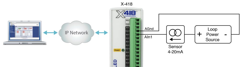
2.9.3 4-20mA Mode
Some industrial sensors output a current instead of voltage levels. Normally, a shunt resistor is needed to measure the current. With the X-412/X-418/X-420, the 4-20mA mode enables an internal precision 200-ohm shunt resistor (0.1%, 25ppm) and automatically configures the A/D for ±5V operation. This feature allows direct connection to 0-20mA current loop transducers. At 20mA, the maximum loop voltage across the input is 4.0 Volts (.020 x 200 = 4.0V). With this setting, the voltage-to-current calculation ((Vin/200)*1000) is automatically made so the measurement is in units of mA.
When connecting more than one 4-20mA sensor consider using a “star” or single point ground topology. If the output current from one sensor changes or affects the measurements of other sensors (crosstalk), you will need to re-consider your connections.
Loop powered current transmitters normally require 7 to 8 Volts across their terminals in order to work properly. With a 200-ohm resistor in the X-412/X-418/X-420 the load resistor will drop an additional 4-Volts. Allow 2-volts or so for voltage drops across the wiring, especially if the wires are small or long. For this example, make certain your loop power source is at least 14-Volts (8+4+2).
2.9.3.1 Monitor Flow, Distance, or Speed with a 4-20mA Sensor
Sensors are available for measuring flow, distance, speed, and many other industrial processes. Many sensors employ a 4-20mA analog output. With the built-in shunt resistors in the X-412/X-418/X-420 these transducers can be connected directly to the X-412/X-418/X-420 as described above. Once the components are properly wired, the X-412/X-418/X-420 must be configured with the proper Slope and Offset to convert the current measurement into engineering units such as CFS (flow), Meters (distance) or Meters per Second (speed). For linear transducers this is normally done with a Y=mX+b equation.
Engineering Value = (Measured Value * Slope) + Offset
The documentation for the sensor must be consulted for the calculations. For example, if the range of a laser rangefinder is 1Meters to 100Meters the transducer will output 4mA at 1M and 20mA at 100M. The X-412/X-418/X-420 makes measurements in units of mA. To convert this measurement to engineering units, the mA measurement must be processed with a Slope setting. The general term for the Slope is:
Slope = (Y2-Y1)/(X2-X1)
To determine the slope, first determine the minimum and maximum current that will be applied to the X-412/X-418/X-420. In this example, the transducer will output 4mA at 1M and 20mA at 100M.
To calculate the slope:
Slope = (100M – 1M)/(20mA – 4mA) = 6.1875 Meters/mA
Once the slope is determined, calculate the offset using the Y=mX+b linear equation where b is the offset.
1M = 6.1875M/mA * 4mA + Offset
Offset = 1M – (6.1875M/mA * 4mA) = -23.75M
2.9.4 Pseudo Digital Inputs
For applications where digital inputs are needed, specific analog inputs can be configured as a pseudo digital input with a boolean (true/false) state. The input voltage is compared to a fixed threshold to determine a true/false state. The input is considered “true” when the voltage rises above 3.5V and “false” when it falls below 1.5V. The analog inputs cannot process narrow pulses or high frequency input changes.
When an analog input is configured as a digital input, the input can be configured to send an email, control a remote relay (over the network), or monitor the state of a discrete device. Note that these Pseudo Digital Inputs do not have the optical isolation that is used in all of the dedicated digital inputs found on other devices in the 400 Series. Without the optical isolation these Pseudo Digital Inputs are not protected as well from transient voltage spikes so it is not recommended that these inputs be used with long cables, outdoor cable runs, or electrically noisy environments.
The illustration below shows an example of using the X-412/X-418/X-420s to monitor the status of a gate or door over an IP network. The status of the device is detected with a simple switch. These type of sensors are called “dry contacts” in that the device output is a bare switch with no power source. In this example a voltage source for the switch is provided by the +5Vref output. A pull-down resistor must be provided to drive the input to a known state (0V) when the switch is open. In this example the measurement voltage will be 5.0V when the switch is closed and 0-V when the switch is open.

2.10 Analog Output Connections (X-417 only)
The analog outputs can be individually programmed to function as 0-5V, 0-10V, ±5V, ±10V, 4-20mA outputs.
Voltage Output Connections
Many variable frequency drives (VFD), servos and other actuators are controlled by a variable voltage. To use these devices the Aout and Com outputs are connected directly to the device to be controlled. A connection must be made to the Com terminal. Internally the Vin- and Com pins are isolated by the DCDC converter. The maximum output current for voltage outputs is 10mA per channel. The five Com pins are internally connected together.
Current Output connections
Some actuators are designed to respond to a change of DC current instead of the voltage levels. To use these devices the Aout and Com outputs are connected directly to the device to be controlled. Power for the current loop is provided by the X-417. The X-417 employs an internal current source for controlling the output current. The current source saturates at 11.5V. As such the resistance of your output current loop must not be more than 575 ohms (575ohm x 0.02A = 11.5V). This includes the input resistance of the actuator and any wiring in the current loop. If the current loop is open or the loop resistance is too high the respective yellow fault LED will be illuminated and the web page display will show the output value as xx.xx.

2.10.1 Digital to Analog Converter
The X-417 accepts output settings in familiar engineering units such as V, M, Ft, KPH, %. Internally the X-417 automatically scales the output settings before setting the digital to analog converter. This allows the user to control the output device using familiar and descriptive engineering units.
The internal calculations are made with a linear slope and offset equation (Y=mX+b). With the default settings, the input and output have a 1 to 1 relationship. For example, with the default settings, setting the output to 2.0 will result in the analog output being 2.0Volts. When the X-417 is controlled via Modbus/TCP from a PLC or other device it may be convenient to leave the default settings undisturbed so that no data scaling is done in the X-417 and any math or other calculations are done in the PLC or controlling device.
If you wish the X-417 to scale and process the output settings, you can access the Analog Outputs tab in the Setup menu to change the output settings. For example, you may wish to control a damper motor and have the display and settings with values of 0 to 100%. When properly configured, the X-417 will scale a setting of 0% to generate a 4.0mA output, and a setting of 100% to generate a 20.0mA output.
2.11 Digital I/O (X-420 Only)
The Digital I/O’s can be individually programmed to function as either inputs or outputs. The digital I/Os employ 5V logic, are not isolated and share a common ground with the power connection.
2.11.1 Digital I/O Configured as Inputs
When a Digital I/O is configured as an input, the input can be configured to send an email, control a remote relay (over the network), monitor the state of a discrete device, or one input can control the other output. The digital inputs work with sensors with switch-closure outputs including push buttons, magnetic door alarm switches, micro-switches, or any device which has a relay, switch-closure or open-collector output. The inputs can be configured for the alarm to be active when the switch is either open or closed.
The illustrations below show an example of using the X-420 to monitor the status of a gate or door over an IP network. The status of the device is detected with a switch.
Pull Resistor
When configured as an input, an internal pull-up or pull-down resistor can be selected in the settings. If no connections are made to the input, the pull-up resistor will pull the input high (on), and the pull-down resistor will pull the input low (off). The illustrations below show how the pull resistors work with simple single pole switches connected to the digital inputs.
For a high-side switch, one side of the switch is connected to the +5V output and the other to I/O 1 or I/O 2. Select the pull-down resistor. When the switch is open, the pull-down resistor pulls the input low (Off).

For a low-side switch, one side of the switch is connected to ground and the other to I/O 1 or I/O 2. Select the pull-up resistor. When the switch is open, the pull-up resistor pulls the input high (On).

2.11.2 Digital I/O Configured as Outputs
When a Digital I/O is configured as an output, it can be used to supply a voltage to an external relay or device. The example below illustrates how the output can be used to actuate an external solid state relay. Note that a solid state relay is used because most electro-mechanical relays would require more current than these digital outputs can provide.

2.12 Frequency Input (X-420 Only)
Sensors that output pulses can be connected to the Frequency Input. The input is AC coupled and is designed for direct connection to a magnetic wind speed sensor. Magnetic wind speed sensors output a low voltage sine wave at low wind speed, as the wind speed increases both the voltage and frequency increase.
The frequency input works with other sensors compatible with an AC input. For example, a 6VAC or 12VAC transformer can be used to measure the AC line frequency or the output frequency of a generator.
2.13 Network Connection

X-418 and WebRelay shown. Same concept applies to all ControlByWeb devices.
Connect the Ethernet port to a standard 10/100/1000 Base-T Ethernet connection. The module typically connects to an Ethernet switch, or router. For configuration, the module may be connected directly to the Ethernet port on a computer or through a switch or router. The module supports auto-negotiation and will work with either crossover or straight-thru cables. It can be also used on a wireless network by connecting through an Ethernet bridge or a wireless router.

X-418 device shown. Same concept applies to all ControlByWeb devices.
Note: The wireless Ethernet bridge or router must be properly configured for the wireless network. Refer to the installation instructions for the wireless device.
2.14 System Start Up
At power-up, the green Power LED should be illuminated. The modules require 10 to 15 seconds to startup before being accessible over the ethernet.
2.15 Establishing Communications for Setup
In order to configure the modules with their built-in web interface, the module must be connected to an Ethernet network. This can be done by one of two methods:
Method 1– Temporarily change the IP address of a connected computer to be compatible (same subnet) with the default IP address used by the module.
Note: If multiple ControlByWeb™ devices are used on the same network, install one at a time and set the IP address of each unit before connecting the next unit to the network. This avoids having multiple devices being installed on the network with the same factory default IP address at the same time. If this approach is used, be sure to clear the arp cache after disconnecting each unit (run ‘arp -d ‘ from an administrative command prompt).
-or-
Method 2 – Assign a temporary IP address to the module to work on an existing network.
2.15.1 Method 1: Assign a Temporary IP Address to the Configuration Computer
By default, the modules come from the factory with an IP address of 192.168.1.2. Communication with the module may be established by assigning an IP address to the configuration computer so that it is on the same logical (and physical) network as the module (for example, the configuration computer could be assigned to an IP address of: 192.168.1.50)
The following example is for those running the Windows 10 operating system:
- First, turn off your Wi-Fi settings.
- Then, open the Control Panel on your Windows 10 computer. Click on the Windows logo in the bottom left corner and type “Control Panel”. You’ll see the Control Panel link in the search results. Click on the Control Panel to open it.
- Find and select the Network and Internet link.

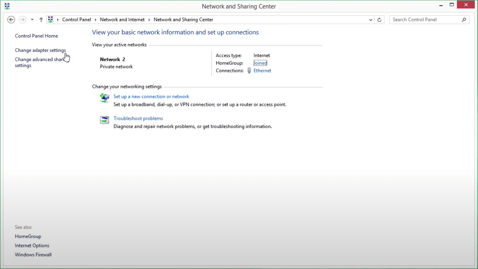
4. Now, select Network and Sharing Center.
5. Next, select the Change adapter settings link in the left sidebar.
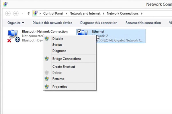
6. Right-click on the Ethernet network and click Properties.
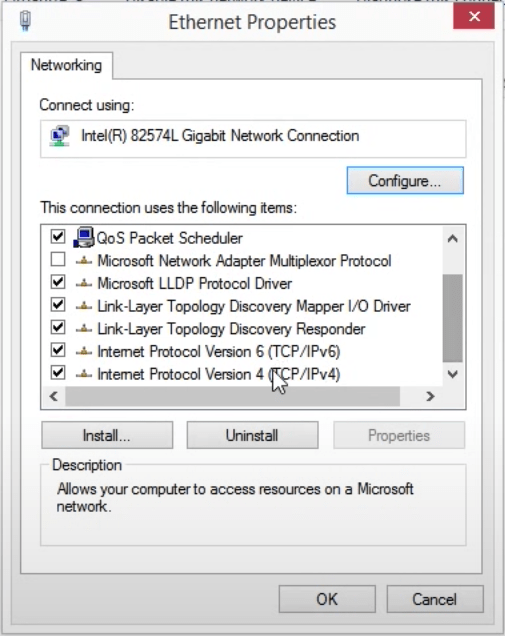
7. You’ll see a list of properties with check boxes. Find the IPv4 property and double-click.
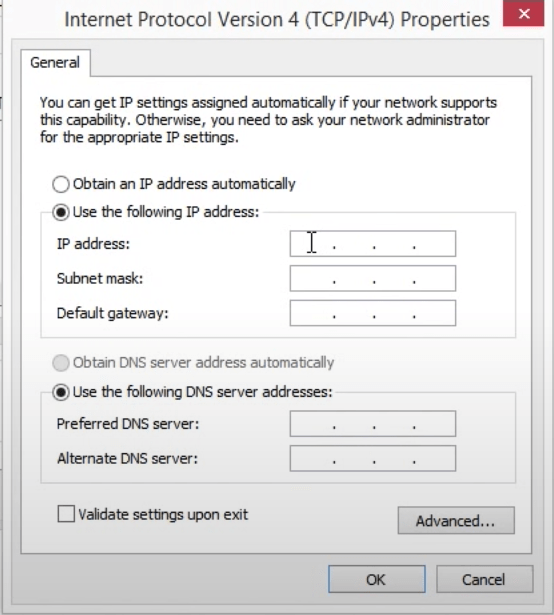
8. Here you’ll find the IP address for your computer. Make note of the current settings so you can restore these settings later. Change your computer’s IP address to 192.168.1.50 and your subnet to 255.255.255.0.
9. Now you can communicate directly with your ControlByWeb device. Open your favorite Internet browser, type in the default IP address, which is 192.168.1.2/setup.html
10. Proceed to enter the default username and password.
11. Visit the Network page under General Settings to assign the new fixed IP address to your ControlByWeb device. This IP address needs to come from your network administrator. If you don’t have a network administrator, you’ll need to find an available IP address on your network.
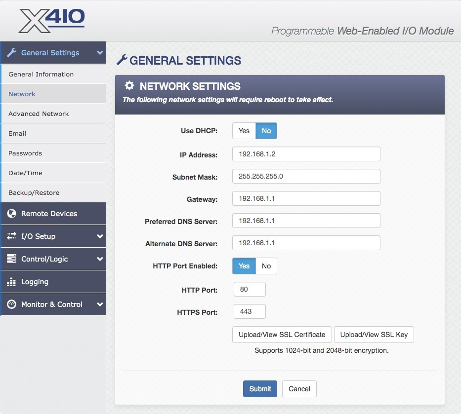
12. Once you’ve changed the IP address on your ControlByWeb device, you need to restore your computer’s network settings. Simply repeat the previous steps (1-5) to access your computer’s Ethernet network settings and restore them to their previous state.
13. You can now access your ControlByWeb device by visiting the new IP address. To change its settings, remember to add /setup.html after the IP address. Now is a good time to change your password, set up your I/O, and add control and alarm logic.
2.15.2 Method 2: Assign a Temporary IP address to the 400 Series module
This option (arp ping) is used to TEMPORARILY assign an IP address to the module without the need to change the IP address of the configuration computer. The module will use this IP address as long as power is maintained. Once power is lost, the module will use the IP address assigned in the setup page and not the temporary address assigned here. Make sure that the module and the configuration computer are connected to the same network. Since ARP is non-routable, this will not work through routers or gateways.
Microsoft Windows Instructions
1. Open a Command Prompt (select START, then RUN, then type “cmd”).
Note: For Vista, 7, 8, and 8.1, the Command Prompt should be run as administrator (select Start, then type “cmd” and right click on “cmd” and select “Run as administrator”).
2. Type:
arp -s {new IP address} {serial number of the ControlByWeb device }
Note: IP address format is xxx.xxx.xxx.xxx. The serial number can be found on a label on the device board. The format is ss-ss-ss-ss-ss-ss.
3. For example, to set the module (with serial number 00-0C-C8-01-00-01 ) to 10.10.10.40 the following command would be used:
arp -s 10.10.10.40 00-0c-c8-01-00-01
4. Next, type:
ping -l 102 {new IP address}
For example, if the new IP address is 10.10.10.40, the following command would be used:
ping -l 102 10.10.10.40
5. Proceed with the module’s setup in Section 3.
Once setup is complete, it may be necessary to clear the ‘arp’ cache to configure additional ControlByWeb devices. This is necessary because each device has the same default IP address, but a different unit serial number (MAC address). Clearing the arp table can be done by typing arp -d in the command prompt window.
Linux/Unix Instructions
1. Open a terminal and change to root user (su -, then enter root password).
2. Type:
arp -s {new IP address} {serial number of the ControlByWeb device }
Note: IP address format is xxx.xxx.xxx.xxx. The serial number can be found on a label on the device board. The format is ss:ss:ss:ss:ss:ss.
For example, to set the module (with serial number 00-0C-C8-01-00-01) to 10.10.10.40 the following command would be used:
arp -s 10.10.10.40 00:0c:c8:01:00:01
3. Next, type:
ping -s 102 {new IP address}
For example, if the new IP address is 10.10.10.40, the following command would be used:
ping -s 102 10.10.10.40
4. Proceed with the module’s setup in Section 3.
Once setup is complete, it may be necessary to clear the ‘arp’ cache to configure additional ControlByWeb devices. This is necessary because each device has the same default IP address, but a different unit serial number (MAC address). Clearing the arp table can be done by typing sudo arp -d -a in the command prompt window.
Mac OS X Instructions
1. Open a terminal.
Note: The terminal is in the “Utilities” directory, which is in the “Applications” directory.
2. Type:
sudo arp -s {new IP address} {serial number of the ControlByWeb device }
Administrator password may be required.
Note: IP address format is xxx.xxx.xxx.xxx. The serial number can be found on the label on the device board. The format is ss:ss:ss:ss:ss:ss.
3. For example, to set the module (with serial number 00-0C-C8-01-00-01 ) to 10.10.10.40 the following command would be used:
sudo arp -s 10.10.10.40 00:0c:c8:01:00:01
4. Next, type:
ping -s 102 {new IP address}
For example, if the new IP address is 10.10.10.40, the following command would be used:
ping -s 102 10.10.10.40
5. Proceed with the device’s setup in Section 3.
Once setup is complete, it may be necessary to clear the ‘arp’ cache to configure additional ControlByWeb devices. This is necessary because each device has the same default IP address, but a different unit serial number (MAC address).
Clearing the arp table can be done by typing sudo arp -d -a in the command prompt window.