Flow monitoring is one of the cornerstones of edge data capture. When properly implemented, flow monitoring ensures that fluids and gases move through systems as intended, giving system administrators actionable data and increasing efficiency.
In this article, we’ll walk through the steps to monitor flow using dry contacts. First, let’s define what a dry contact is.
What Are Dry Contacts?
Dry contacts, also known as potential-free or volt-free contacts, are a type of switch that does not supply any voltage or current on its own. Instead, they rely on an external source to activate. These contacts are commonly used in flow monitoring systems because of their versatility, durability, and ease of integration with various control systems. (ControlByWeb® inputs require a low-voltage DC signal to operate, so a DC voltage must pass through the contact into the ControlByWeb input; wiring may vary from module to module.)
Monitoring flow using dry contacts offers several advantages. They’re straightforward to install and configure, making them ideal for both new installations and retrofits. With no internal power supply, dry contacts are less prone to electrical failures and can operate in harsh environments. They can also be integrated with a wide range of flow sensors and control systems.
Components Needed
To monitor flow using dry contacts, you’ll need the following components:
- Flow sensor: A device that detects and measures the flow rate of the fluid or gas. A dry contact relay component is pulsed based on a specific volume (for example, 1 pulse per X gallons).
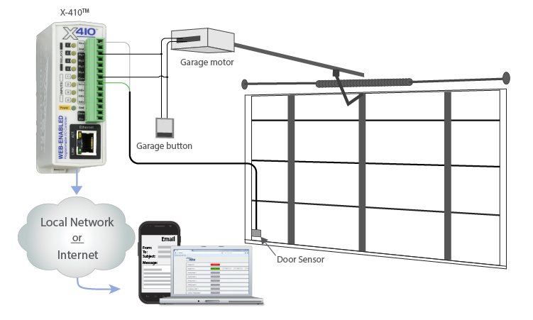
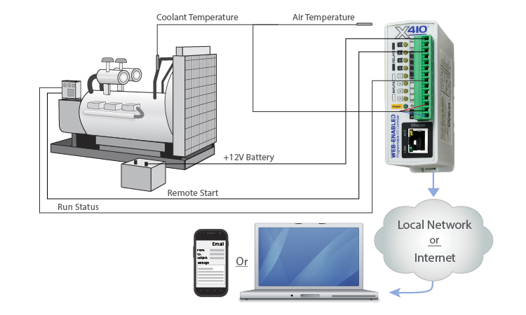
- An I/O module: A digital input controller, such as the X-410™ or X-408™, can interface with the dry contact relay and provide monitoring and alerting capabilities that go beyond a traditional simple data gateway.
- Wiring and connectors: Appropriate wiring and connectors to link the sensor, relay, and I/O module.
- Additional considerations: You will also need appropriate power supplies and possibly mounting hardware.

Determine the best products for your application with our Sales Engineers.
Step-by-Step Instructions
1. Install the Flow Sensor
Begin by installing the flow sensor in your system. The installation process will vary depending on the type of flow sensor you are using. Consult the product manual.
2. Connect the Flow Sensor & Dry Contact Relay
Typically, a flow meter will already have a reed switch contact, which is itself a dry contact. (Most flow meters can be connected directly to a ControlByWeb controller.) If the dry contact is separate, follow the wiring diagram provided by the flow sensor manufacturer to connect with the contact. Test the setup to ensure the flow sensor activates the dry contact relay properly.
3. Integrate the Dry Contact Relay with the I/O Module
Use appropriate connectors and wiring to link the output terminals of the dry contact relay to the input terminals of the I/O module (e.g., X-410 or X-420). Refer to the 400 Series user manual for details. Once connected, access the ControlByWeb device’s web interface to configure the input channel corresponding to the dry contact relay. Set it up as a counter to monitor the state changes and generate alerts or log data accordingly.
4. Set Up Alerts and Data Logging
Configure your ControlByWeb device to send email and SMS alerts. This could include conditional alerts for when flow sensor detecting abnormal flow rates to help in promptly addressing any issues in the system. Enable data logging directly through the device to keep track of flow rates over time. This is useful for analyzing trends and making informed decisions for system maintenance and optimization.
5. Test the Complete Setup
Simulate different flow conditions to ensure the entire setup—from the sensor to the I/O module—is working correctly. Verify that alerts are triggering as expected and data is logging accurately.
Optional: Integrate with SCADA System
ControlByWeb modules have an easy-to-use embedded UI for logical control, but they also work perfectly well with third-party systems. Connect the I/O module to your SCADA using a supported communication protocol such as Modbus TCP/IP or HTTP GET. Learn more about our open REST API.
6. Regular Maintenance and Calibration
Perform regular maintenance checks to ensure all components are functioning correctly. Clean sensors and check wiring for any signs of wear or damage. It may be necessary to periodically calibrate flow sensors to maintain accurate readings. Follow the manufacturer’s guidelines for calibration procedures.
ControlByWeb®: Much More Than a Gateway
There are a lot of variables to account for across edge data applications and this article only scratches the surface. If you’re looking to monitor flow or have other IIoT applications in mind, consult our sales engineers to determine the best solution. Our I/O controllers offer amazing flexibility at a fraction of the cost of a traditional PLC, ensuring that you have what you need for your next project.
For help with your industrial application, contact our team or schedule a 15-minute product demo.
Subscribe to Our Newsletter
Subscribe to Our Newsletter
Sign up for our newsletter to receive information regarding new products and exclusive offers.